KS0464 Smart Turtle Robot Car V3.0
1. Introduction
Nowadays, technological education such as VR, kids programming, and artificial intelligence, has become mainstream in educational industry. Thereby, people attach importance to STEAM education.
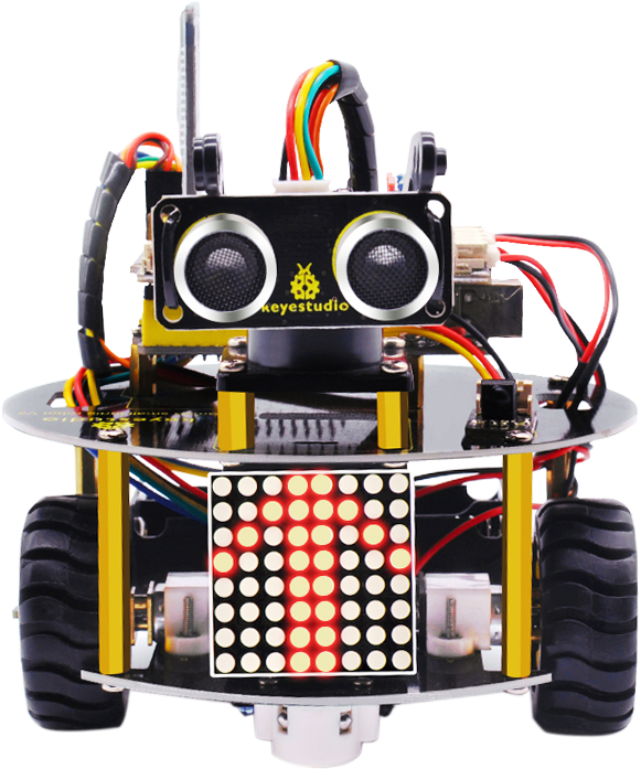
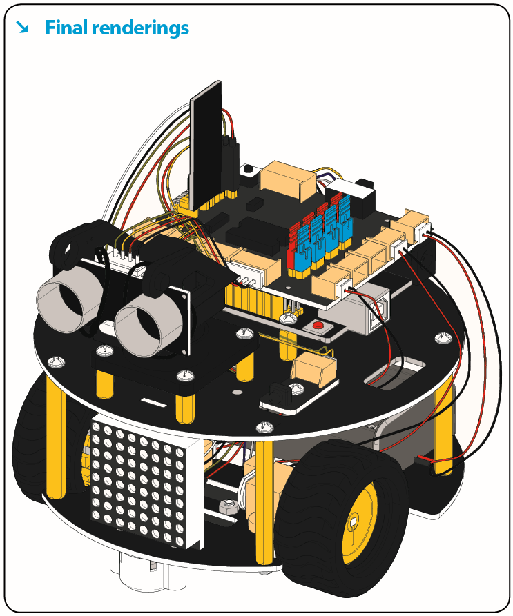
The turtle multi-purpose robot car, newly upgraded by the Keyes team, is one of the most favored programming robots.
It is not only beautiful in appearance, but also powerful in function. In addition to the common function like line tracking, obstacle avoidance and remote control, etc.
15 learning projects, from simple to complex, will guide you how to make a smart turtle robot on you own and introduce the detailed knowledge about sensors and modules.
Simultaneously, it is the best choice if you intend to obtain a DIY robot for learning programming, entertainment and competition requirement.
2. Features
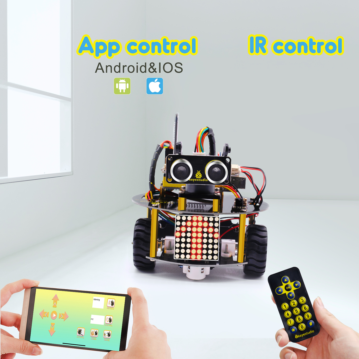
1.Multi-purpose function: Obstacle avoidance, follow, IR remote control, Bluetooth control, ultrasonic follow and displayed face emoticons.
2.Simple assembly: No soldering circuit required, complete assembly easily.
3.High Tenacity: Aluminum alloy bracket, metal motors, high quality wheels and tracks.
4.High extension: expand other sensors and modules through motor driver shield and sensor shield.
5.Multiple controls: IR remote control, App control(IOS and Android system)
6.Basic programming:Mixly programming.
3. Specification
Working voltage: 5v
Input voltage: 7-12V
Maximum output current: 2A
Maximum power dissipation: 25W (T=75℃)
Motor speed: 5V 200 rpm/min
Motor drive mode: dual H bridge drive
Ultrasonic induction angle: <15 degrees
Ultrasonic detection distance: 2cm-400cm
Infrared remote control distance: 10 M (at the open environment without interference)
Bluetooth remote control distance: 35-50 M at the open environment without interference)
Bluetooth control: support Android and iOS system
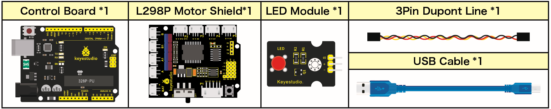
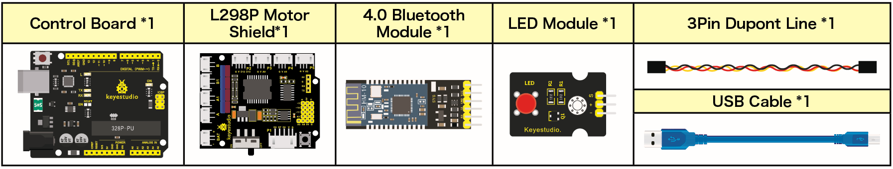
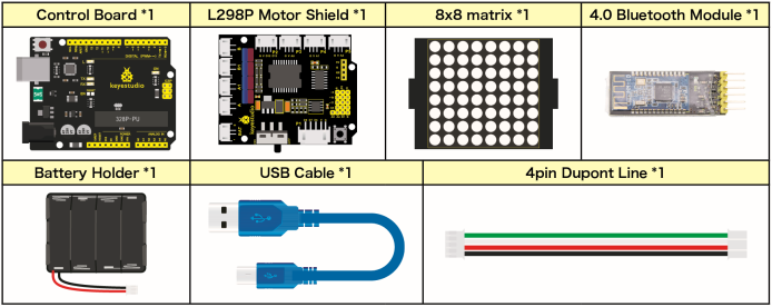
4. Product List

NO |
NAME |
QTY |
PIC |
|---|---|---|---|
1 |
V4.0 Board (UNO compatible) |
1 |
|
2 |
Quick Connectors Motor Driver Shield |
1 |
|
3 |
Quick Connectors IR Receiver |
1 |
|
4 |
Quick Connectors Line Tracking Sensor |
1 |
|
5 |
Quick Motor Connector A & B |
2 |
|
6 |
8*8 Dot Matrix Module |
1 |
|
7 |
Quick Connectors Ultrasonic Module |
1 |
|
8 |
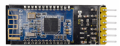
Bluetooth Module(HC-06) |
1 |
|
9 |
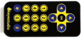
JMFP-4 17 Remote Control(without batteries) |
1 |
|
10 |
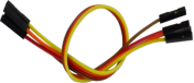
15CM 5P 24AWG Wire |
1 |
|
11 |
8CM 4P 24AWG Wire |
1 |
|
12 |
8CM 3P 24AWG Wire |
1 |
|
13 |
160mm 2P 24AW Wire |
2 |
|
14 |
Battery Holder with JST-PH2.0MM-2P Lead |
1 |
|
15 |
4 Slot AA Battery Holder |
1 |
|
16 |
M2*12MM Round Head Screws |
4 |
|
17 |
M2 Nickel Plated Nuts |
4 |
|
18 |
M3*6MM Round Head Screws |
27 |
|
19 |
M3*6MM Flat Head Screws |
2 |
|
20 |
M3 Nickel Plated Nuts |
5 |
|
21 |
M3*10MM Hexagon Copper Bush |
8 |
|
22 |
M3*40MM Hexagon Copper Bush |
4 |
|
23 |
9G Servo |
1 |
|
24 |
N20 Motor Wheel |
2 |
|
25 |
N20 Motor U Type Mount |
2 |
|
26 |
Black Plastic Platform |
1 |
|
27 |
3PI MiniQ Universal Caster |
2 |
|
28 |
3*40MM Black-yellow Screwdriver |
1 |
|
29 |
1m Transparent Blue USB Cable |
1 |
|
30 |
3*100MM Black Ties |
5 |
|
31 |
Turtle Robot Baseboard |
1 |
|
32 |
Turtle Robot Top Board |
1 |
|
33 |
F-F 20CM/40PDupont Cable |
1 |
|
34 |
20cm 3pin F-F Dupont Cable |
1 |
|
35 |
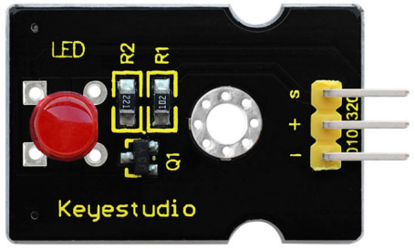
Red LED Module |
1 |
|
36 |
Decorative Board |
4 |
|


5. Assembly Guide
Note: Peel the plastic film off the board first when installing the smart car. To be honest, we never intend to send wood to you.
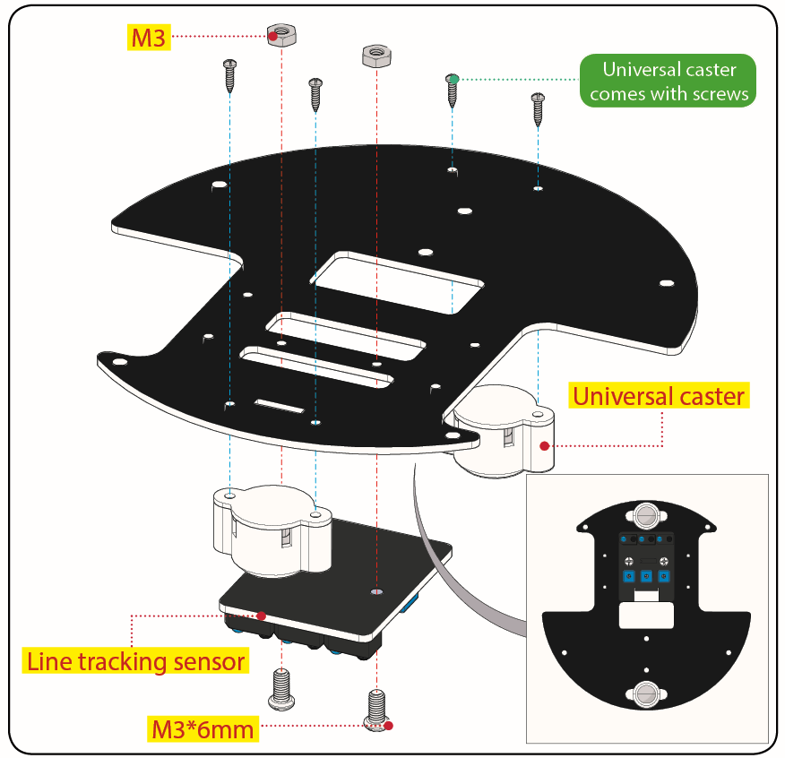
Step 1: Mount Motor Wheel
M3*6MM Round Head Screw *2
M3*6MM Flat Head Screw *2
M3 Nickel Plated Nut *2
Bottom PCB*1
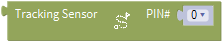
Tracking Sensor *1
Universal Caster *2
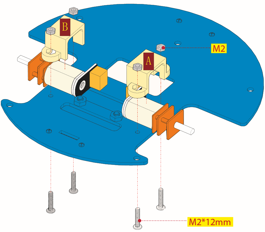
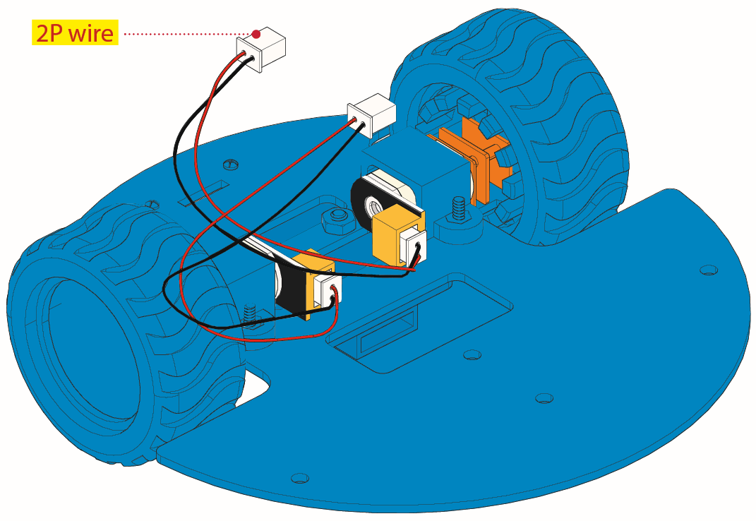
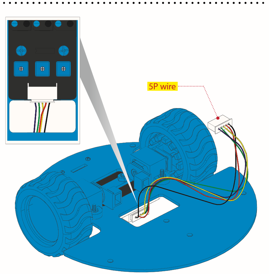
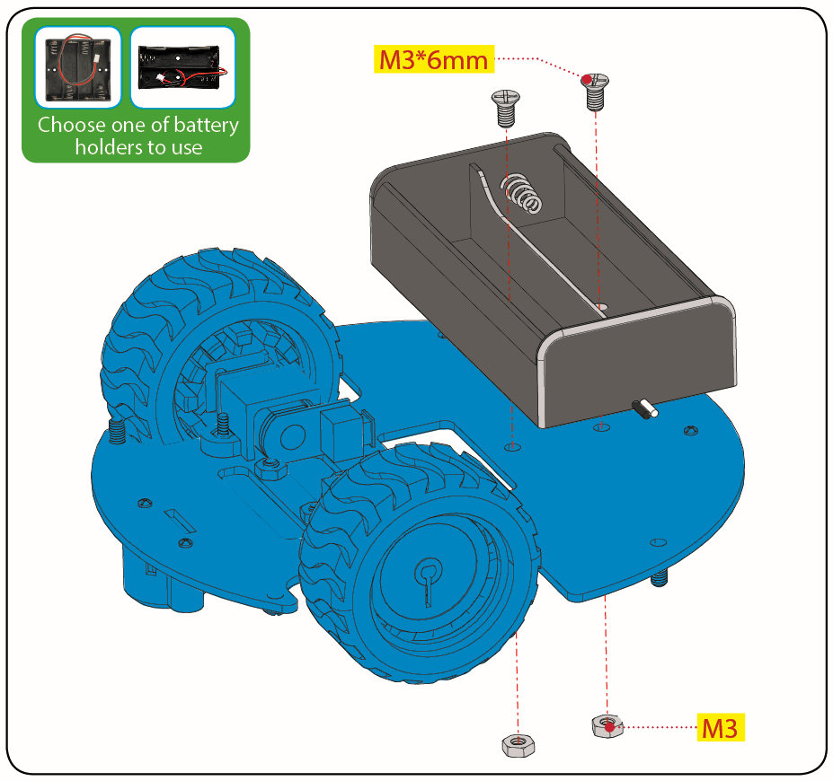
Step 2: Assemble Parts
Prepare the parts as follows:
M3*6MM Round Head Screw *2
M2 Nut *4
12FN20 Motor *2
U-type Holder* 2
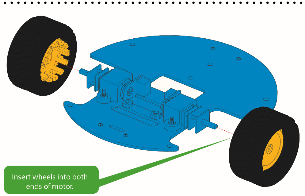
N20 Motor Wheel *2
2P Wire *2
5P Wire *1
M2*12MM Round Head Screw *4
2-cell AA Battery Holder *1
M3*6M Flat Head Screw *2
M3 Nut *2
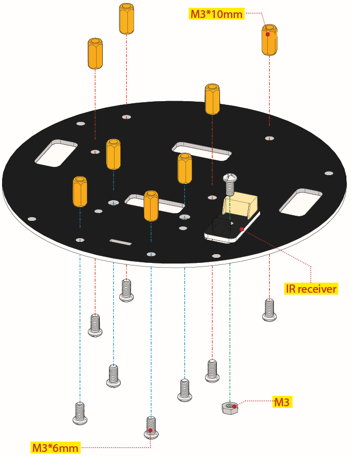
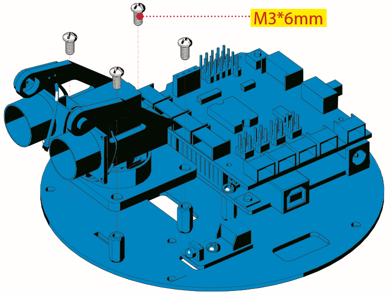
Step 3: Install Top PCB
Prepare the parts as follows:
Top PCB *1
M3 Nut *1
M3*6MM Round Head Screw *9
M3*10MM Hexagon Copper Bush *8
IR Receiver Sensor *1
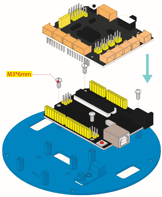
Step 4: Mount Control Board
Prepare the parts as follows:
V4.0 board*1
Motor Drive Shield V2*1
M3*6MM Round Head Screw *4
M3*6MM round-head screw *4
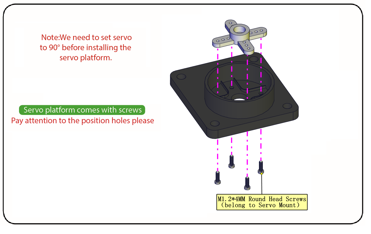
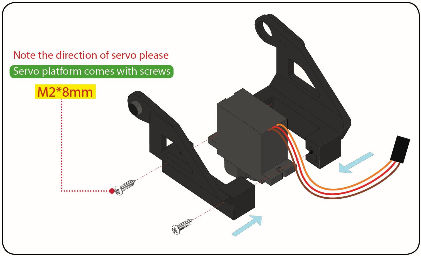
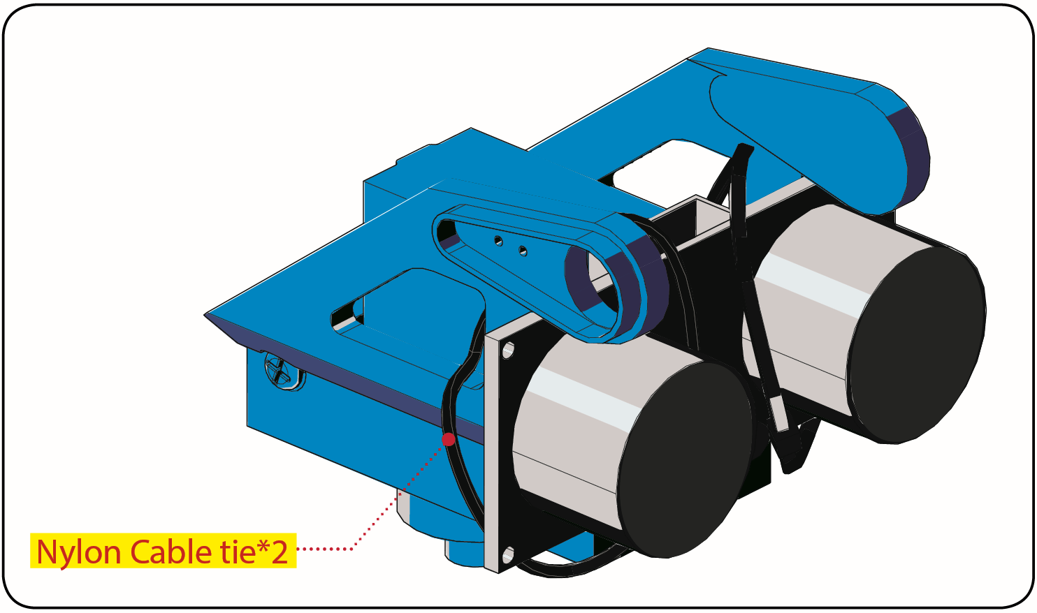
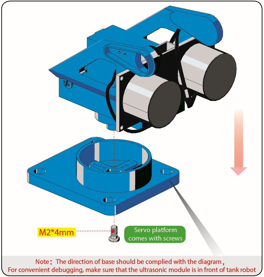
Step 5: Servo Plastic Platform
Prepare the parts as follows:
Servo *1
M2*4 Screw *1
Black Tie*2
Ultrasonic Sensor*1
Black Plastic Platform *1
M1.2*4 Tapping Screw *4
M2*8 Tapping Screw *2
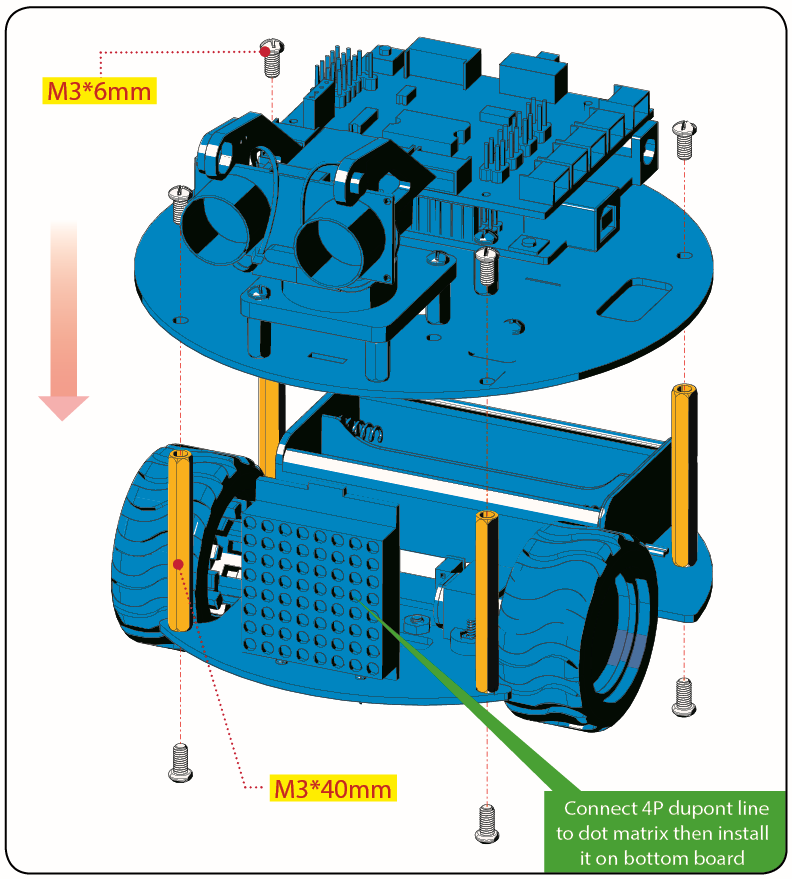
Step 6: Final Assembly
Prepare the parts as follows:
M3*6MM Round Head Screw *12
M3*40MM Hexagon Copper Bush*4
8x8 Dot Matrix *1
Jumper Wire *4
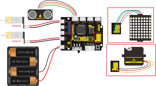
Step 7: Hook-up Guide
6.Install Mixly Software and Driver
1. Download and Install Mixly
①Description
Mixly is a free open-source graphical Arduino programming software, based on Google’s Blockly graphical programming framework, and developed by Mixly Team@ BNU.
It is a complete support ecosystem for creative e-education, a stage for maker educators to realize their dreams.
② Download Mixly1.0
Windows System:https://fs.keyestudio.com/Mixly1-Windows
MACOS System:https://fs.keyestudio.com/Mixly1-MACOS
We will take Mixly1.0 (Windows version) as example, and the installation method of MAC version is similar with it.
You will get installation package after downloading. As shown below:
Unzip the package, you will see “Mixly 1.0 for keyestudio.exe”
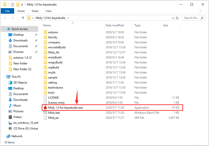
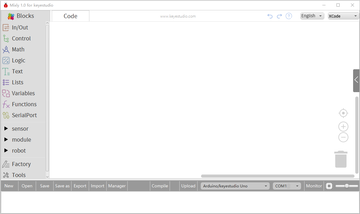
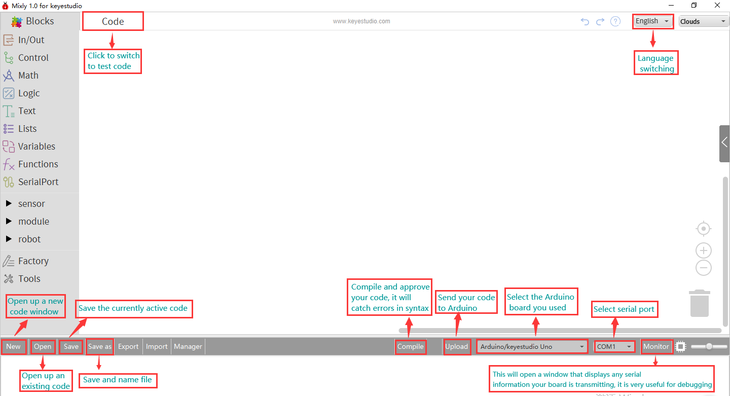
Double-click  ”Mixly 1.0 for keyestudio.exe”, the following interface pops up.
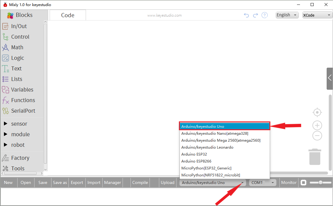
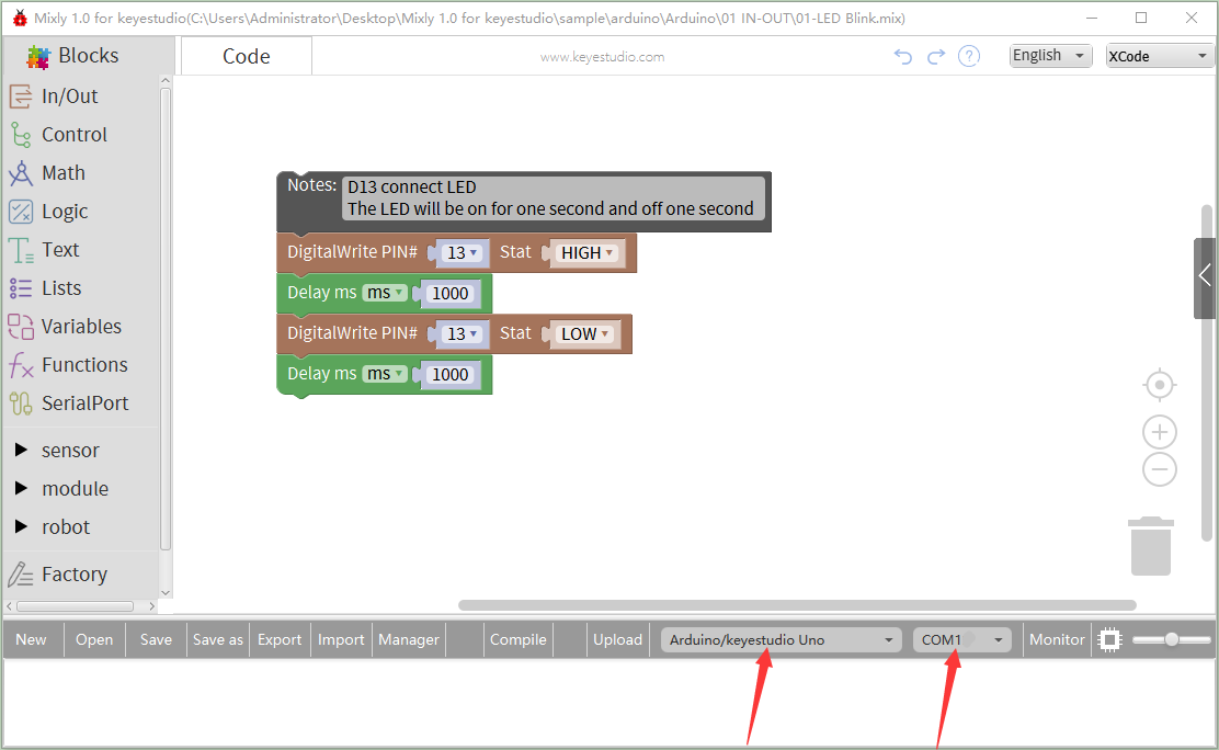
We have to choose correct Arduino development board and name, as shown below:
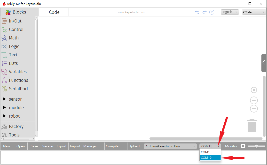
Select correct COM port(the corresponding port will be shown after installing driver successfully)
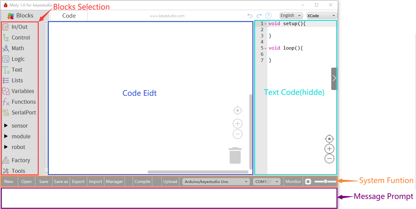
You have to know the function of every area and interface on Mixly software before uploading program on Arduino development board.
2. Keyestudio V4.0 Development Board
We need to know keyestudio V4.0 development board, as a core of this smart car.
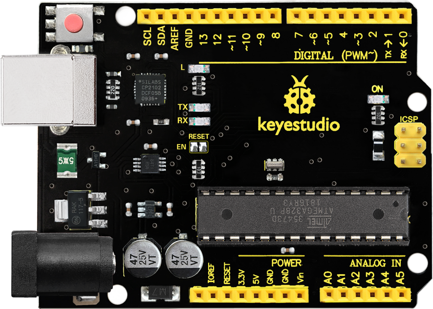
Keyestudio V4.0 development board is an Arduino uno -compatible board, which is based on ATmega328P MCU, and with a CP2102 Chip as a UART-to-USB converter.
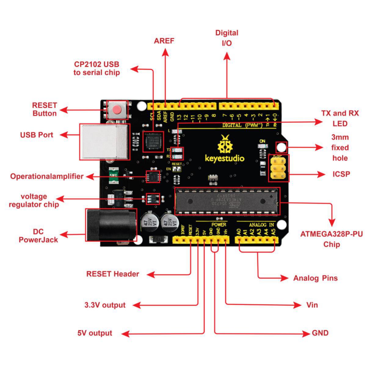
It has 14 digital input/output pins (of which 6 can be used as PWM outputs), 6 analog inputs, a 16 MHz quartz crystal, a USB connection, a power jack, 2 ICSP headers and a reset button.
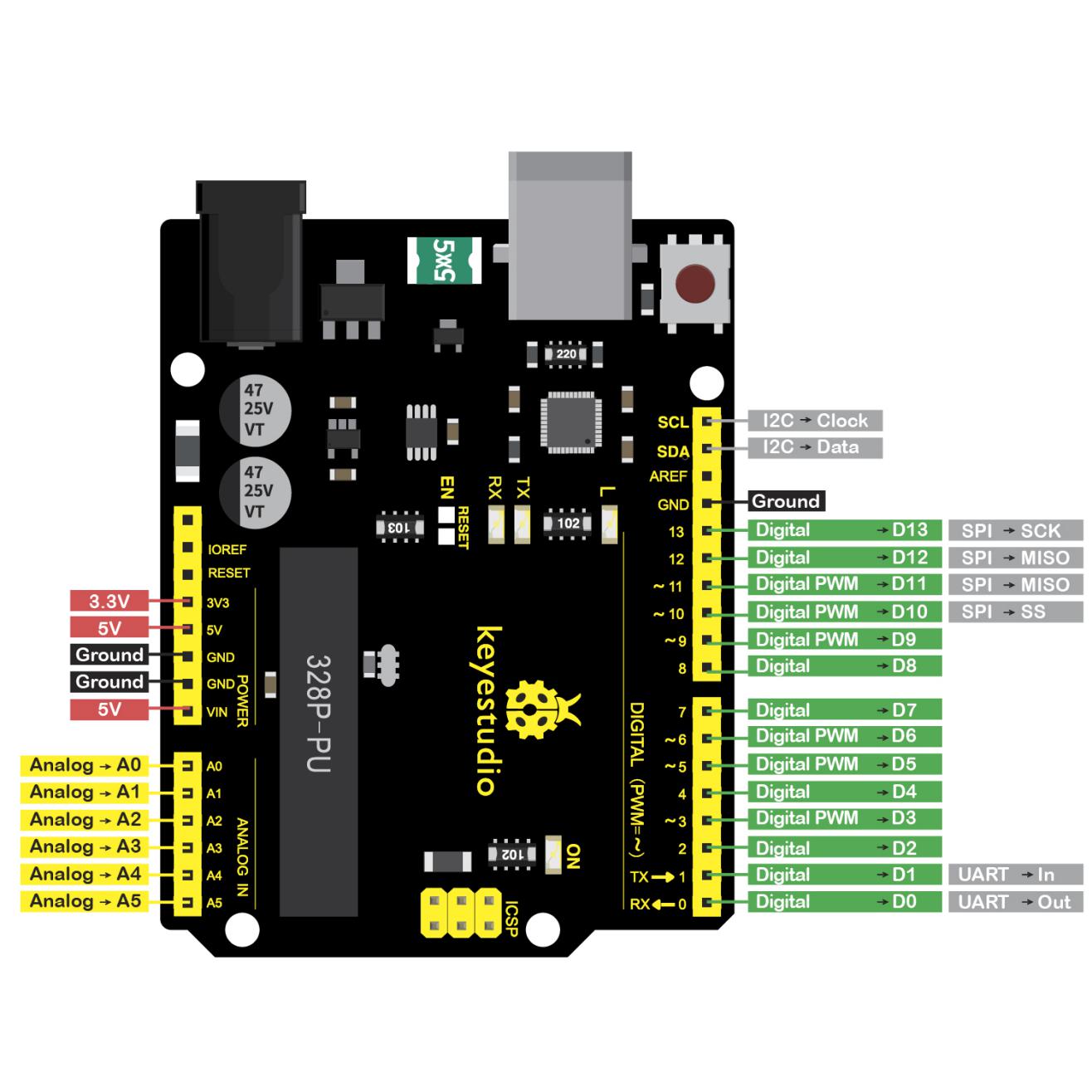
It contains everything needed to support the microcontroller; simply connect it to a computer with a USB cable or power it via an external DC power jack (DC 7-12V) or via female headers Vin/ GND(DC 7-12V) to get started.
Microcontroller |
ATmega328P-PU |
|---|---|
Operating Voltage |
5V |
Input Voltage (recommended) |
DC7-12V |
Digital I/O Pins |
14 (D0-D13) (of which 6 provide PWM output) |
PWM Digital I/O Pins |
6 (D3, D5, D6, D9, D10, D11) |
Analog Input Pins |
6 (A0-A5) |
DC Current per I/O Pin |
20 mA |
DC Current for 3.3V Pin |
50 mA |
Flash Memory |
32 KB (ATmega328P-PU) |
SRAM |
2 KB (ATmega328P-PU) |
EEPROM |
1 KB (ATmega328P-PU) |
Clock Speed |
16 MHz |
LED_BUILTIN |
D13 |
3. Installing V4.0 board Driver
Let’s install the driver of keyestudio V4.0 board. The USB-TTL chip on V4.0 board adopts CP2102 serial chip. The driver program of this chip is included in Arduino 1.8 version and above, which is convenient. Plug on USB port of board, the computer can recognize the hardware and automatically install the driver of CP2102.
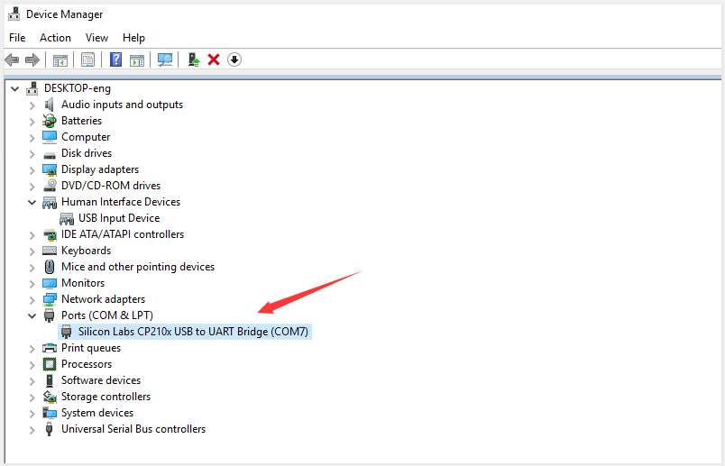
If install unsuccessfully, or you intend to install manually, open the device manager of computer. Right click Computer—– Properties—– Device Manager
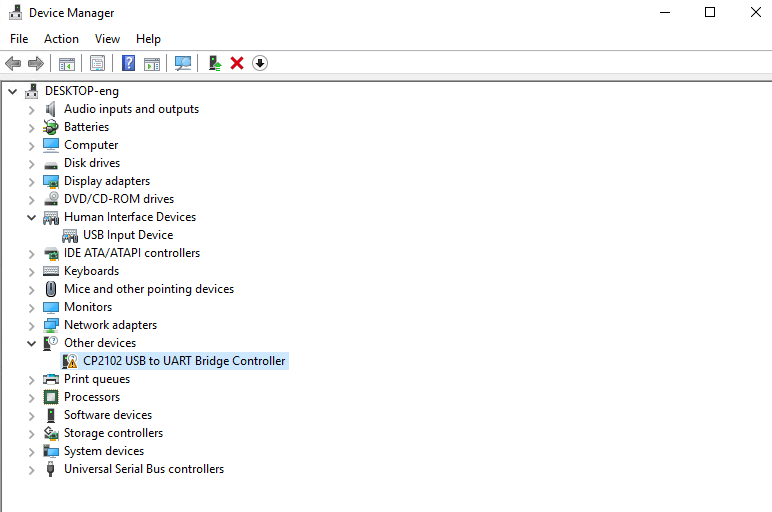
There is a yellow exclamation mark on the page, which implies installing unsuccessfully. Then we double click the hardware and update the driver.
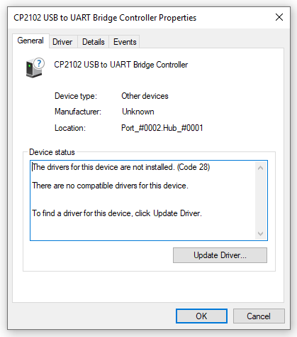
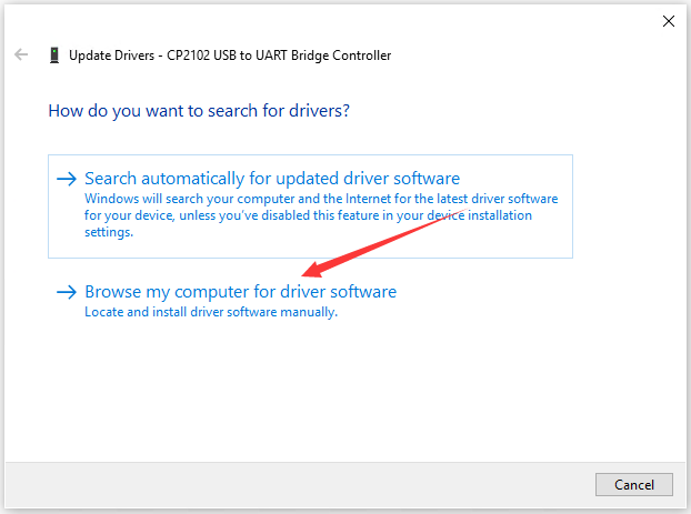
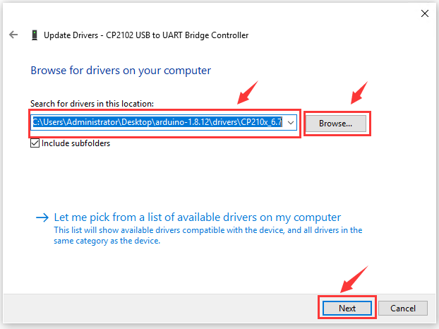
Click “OK” to enter the following page, click “browse my computer for updated driver software”, find out the installed or downloaded ARDUINO software. As shown below:
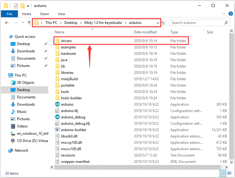
There is a DRIVERS folder in Arduino software installed package( ), open driver folder and you can see the driver of CP210X series chips.


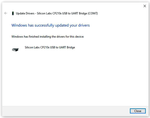
We click “Browse”, then find out the driver folder, or you could enter “driver” to search in rectangular box, then click “next”, the driver will be installed successfully. (I place Arduino software folder on the desktop, you could follow my way)
Open device manager, we will find the yellow exclamation mark disappear. The driver of CP2102 is installed successfully.
4. Start the first program
Click “Open”→ sample → arduino→ Arduino → 01 IN-OUT→01-LED Blink.mix
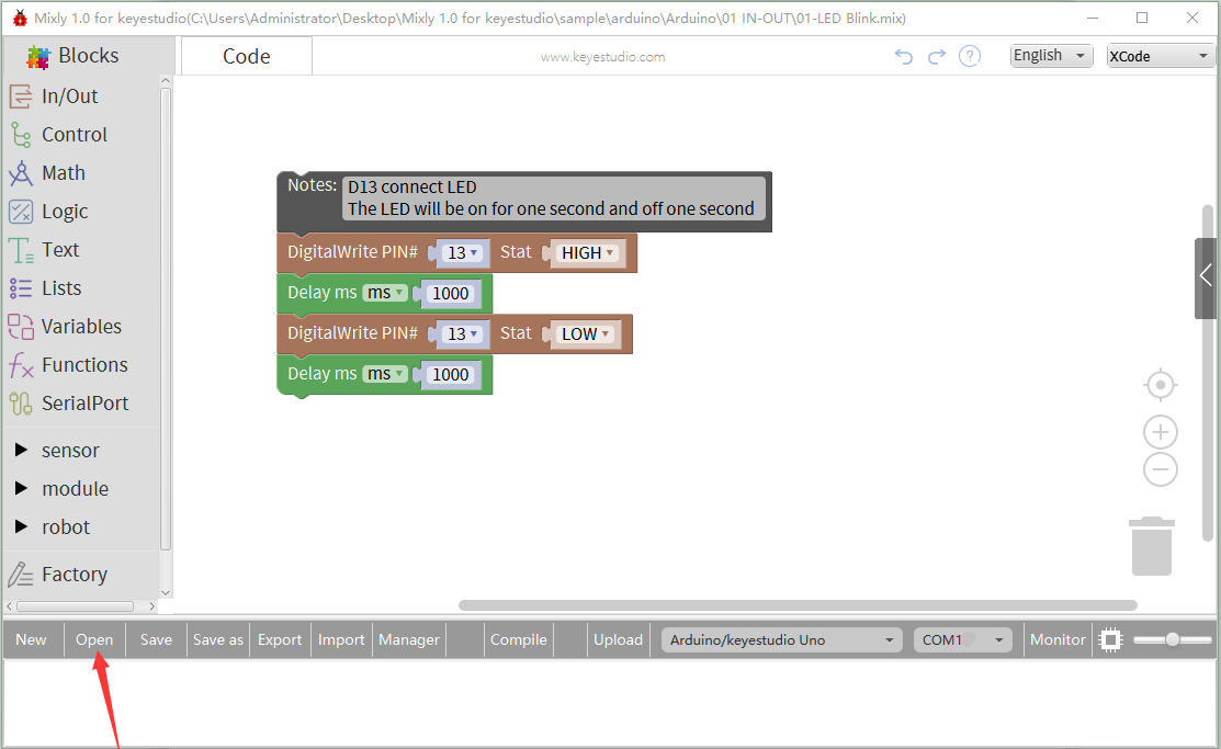
The corresponding board and COM port will be shown after setting board and COM port.
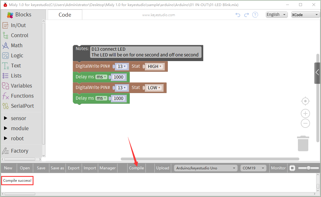
Click Compile to start compiling the program, check errors.
Click Upload to upload the program, upload successfully.
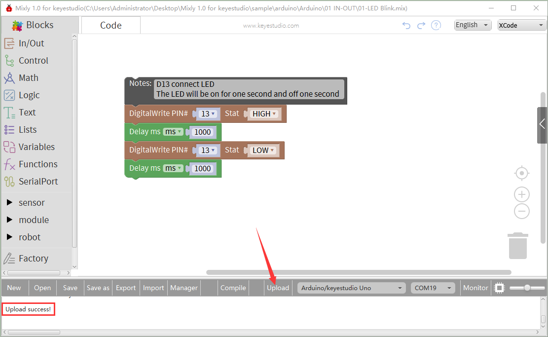
After uploading the program successfully, the on-board LED blinks for 1s.
Congratulation, you finish the first program.
7. Projects:
The whole project begins with basic program. Starting from simple to complex, the lessons will guide you to assemble robot car and absorb the knowledge of electronic and machinery step by step. I reckon that you could hardly sit still and itch to have a go, let’s get started.
Note: (G), marked on each sensor and module, implies negative pole, which is connected to “G”, ”-”or “GND”on the sensor shield and control board ; (V) represents positive pole, which is linked with V , VCC, + or 5V on the sensor shield and control board.
Project 1: LED Blink
1. Description
For the starter and enthusiast, this is a fundamental program—LED Blink.
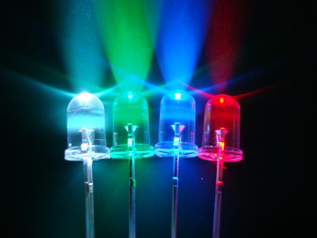
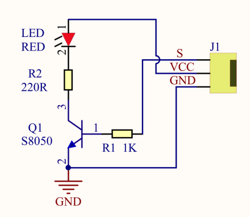
LED, the abbreviation of light emitting diodes, consist of Ga, As, P, N chemical compound and so on. The LED can flash diverse color by altering the delay time in the test code. When in control, power on GND and VCC, the LED will be on if S end is high level; nevertheless, it will go off.
2. Specification
Control interface:
digital port
Working voltage: DC 3.3-5V
Pin spacing: 2.54mm
LED display color: red
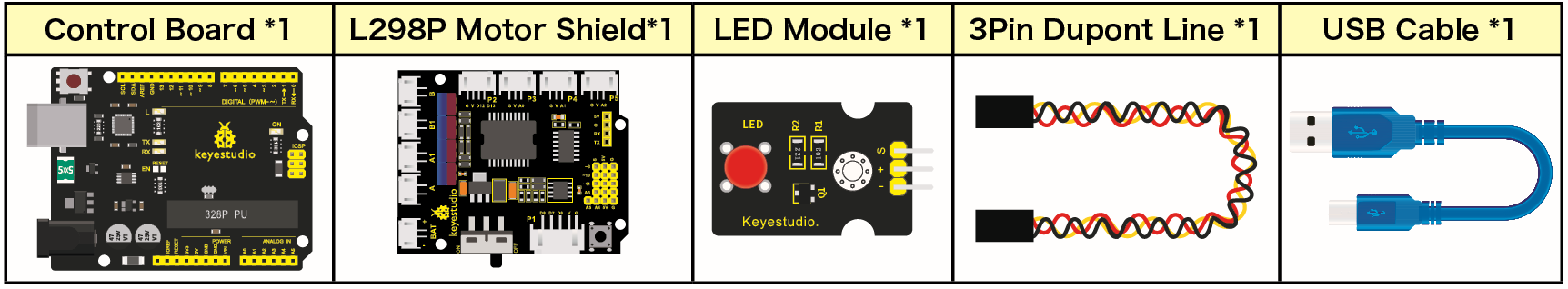
3. Components
4. Wiring Diagram
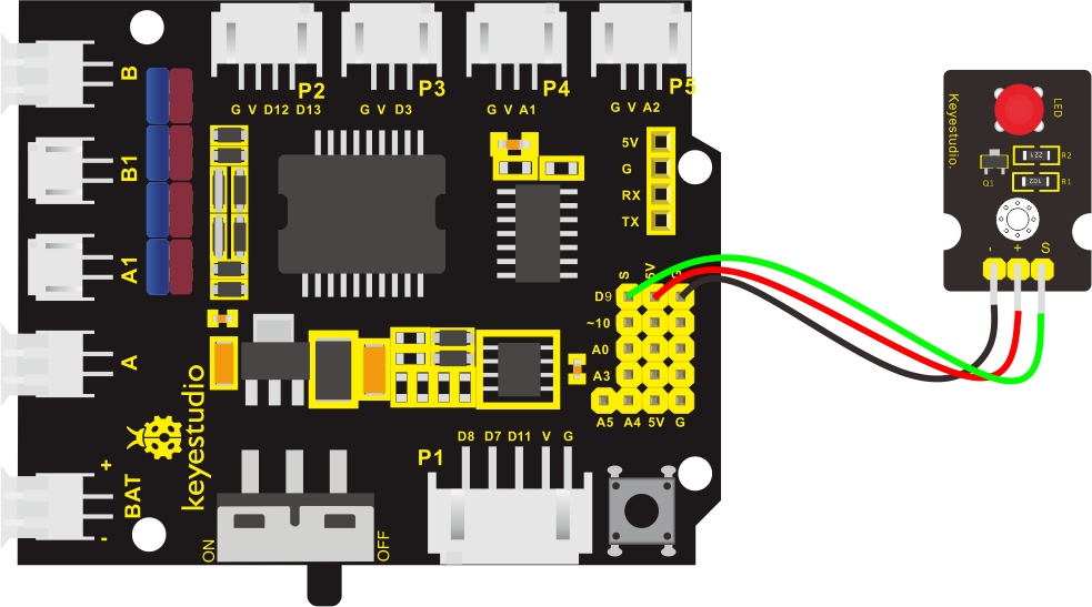
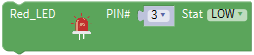
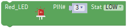
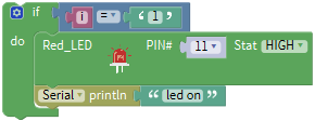
The expansion board is stacked on development board, - of LED module is connected to G of shield,“+”is linked with 5V, S end is attached to D3.
5. Test Code
The program will be generated if you find the following file and drag it into Mixly software.
File type |
Route |
File Name |
|---|---|---|
MIX File |
../tutorial for Mixly/Mixly Code/lesson_1_LED Blink |
lesson_1.1_LED Blink |
You could edit code step by step as follows:
Enter“Control”to get block

Click“Sensor” →“ControlOutput”→
 ,and combine it with block,
S end of red LED is connected D3 of sensor shield, click the drop-down triangle button to set PIN 3 and LOW.
 

- Copy block
 once,and set to HIGH
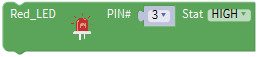
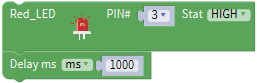
Click “Control” to drag outblock

- Duplicate code stringonce,and set to LOW.
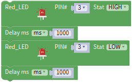
Complete Program:

6. Test Result
Upload the program, LED connected to D9 flickers with the interval of 1s.
7. Extension Practice
We succeed to blink LED. Next, let’s observe how LED will change if we modify pins and delay time.
The program will be generated if you find the following file and drag it into Mixly software.
File type |
Route |
|---|---|
MIX File |
../tutorial for Mixly/Mixly Code/lesson_1_LED blink |
File Name |
|
lesson_1.2_Extension Practice |
You could edit code step by step as follows:
Complete Program:

The LED flickers faster through the test result, therefore, pins and delay time could affect flash frequency.
Project 2: Adjust LED Brightness
1. Description
In previous lesson, we control LED on and off and make it blink.
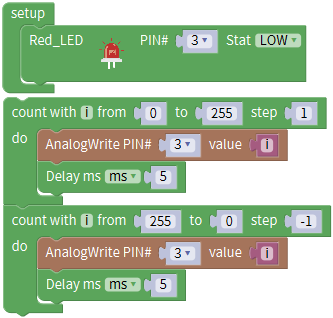
In this project, we will control LED brightness through PWM to simulate breathing effect. Similarly, you can change the step length and delay time in the code so as to demonstrate different breathing effect.
PWM is a means of controlling the analog output via digital means. Digital control is used to generate square waves with different duty cycles (a signal that constantly switches between high and low levels) to control the analog output.In general, the input voltage of port are 0V and 5V. What if the 3V is required? Or what if switch among 1V, 3V and 3.5V? We can’t change resistor constantly. For this situation, we need to control by PWM.

For the Arduino digital port voltage output, there are only LOW and HIGH, which correspond to the voltage output of 0V and 5V. You can define LOW as 0 and HIGH as 1, and let the Arduino output five hundred 0 or 1 signals within 1 second.
If output five hundred 1, that is 5V; if all of which is 1, that is 0V. If output 010101010101 in this way then the output port is 2.5V, which is like showing movie. The movie we watch are not completely continuous. It actually outputs 25 pictures per second. In this case, the human can’t tell it, neither does PWM. If want different voltage, need to control the ratio of 0 and 1. The more 0,1 signals output per unit time, the more accurately control.
PWM is a technology to obtain analog quantity through digital method. Digital control forms a square wave, and the square wave signal only has two states of turning on and off (that is, high or low levels). By controlling the ratio of the duration of turning on and off, a voltage varying from 0 to 5V can be simulated. The time turning on(academically referred to as high level) is called pulse width, so PWM is also called pulse width modulation.
Through the following five square waves, let’s acknowledge more about PWM.
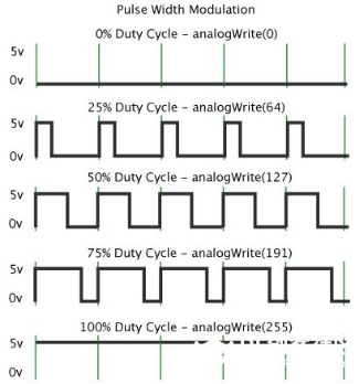
In the above figure, the green line represents a period, and value of analogWrite() corresponds to a percentage which is called Duty Cycle as well. Duty cycle implies that high-level duration is divided by low-level duration in a cycle. From top to bottom, the duty cycle of first square wave is 0% and its corresponding value is 0. The LED brightness is lowest, that is, turn off. The more time high level lasts, the brighter the LED. Therefore, the last duty cycle is 100%, which correspond to 255, LED is brightest. 25% means darker.
PWM mostly is used for adjusting the LED brightness or rotation speed of motor.
It plays vital role in controlling smart robot car. I believe that you can’t wait to enter next project.
2. Components
3. Wiring Diagram
4. Test Code
The program will be generated if you find the following file and drag it into Mixly software.
File type |
Route |
File Name |
|---|---|---|
MIX File |
../tutorial for Mixly/Mixly Code/lesson_2_Adjust LED Brightness |
lesson_2.1_Adjust LED Brightness |
You could edit code step by step as follows:
Click“Control” to get block
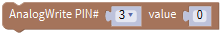
Go to“sensor”→“ControlOutput”→
→,and set to LOW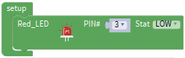
Red LED is connected to D3, so set to PIN 3 and LOW
Enter“Control”to get block
 ,set block:
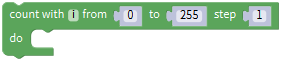
Enter “In/Out” to get block
 ,
,Click “Variables” to move block
 into 0 box behind value.
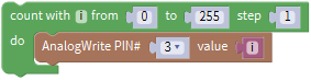
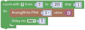
Click ”Control”to move block
into block,delay in 5ms.
Copy code string
once,set code string as follows:
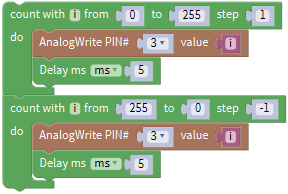
Complete Program:
5. Test Result
Upload test code successfully, LED gradually becomes brighter then darker, like human breath, rather than light on and off immediately.
6. Extension Practice
The program will be generated if you find the following file and drag it into Mixly software.
File type |
Route |
|---|---|
MIX File |
../tutorial for Mixly/Mixly Code/lesson_2_Adjust LED Brightness |
File Name |
|
lesson_2.2_Extension Practice |
You could edit code step by step as follows:
Complete Program:

Upload the code to development board, LED flickers more slowly.
Project 3 : Line Tracking Sensor
1. Description
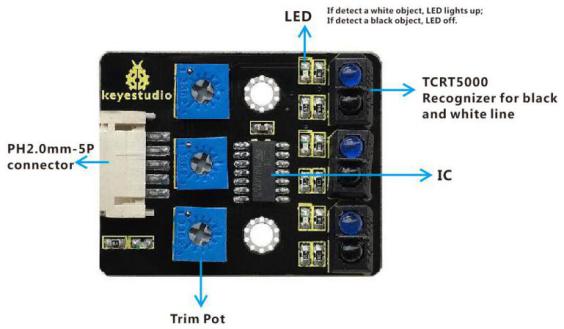
The tracking sensor is actually an infrared sensor. The component used here is the TCRT5000 infrared tube.
Its working principle is to use the different reflectivity of infrared light to the color, then convert the strength of the reflected signal into a current signal.
During the process of detection, black is active at HIGH level, but white is active at LOW level. The detection height is 0-3 cm.
Keyestudio 3-channel line tracking module has integrated 3 sets of TCRT5000 infrared tube on a single board, which is more convenient for wiring and control.
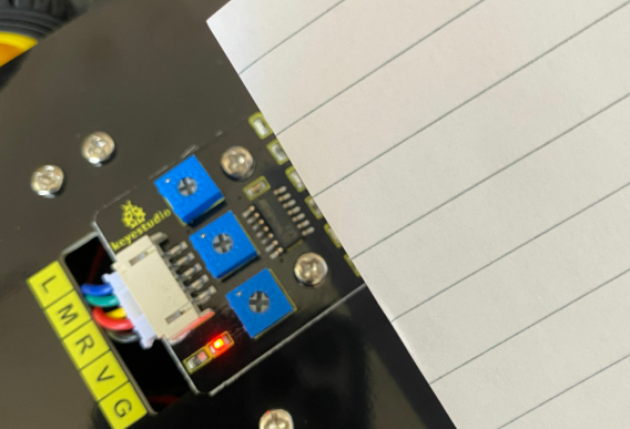
By rotating the adjustable potentiometer on the sensor, it can adjust the detection sensitivity of the sensor.
2. Specification
Operating Voltage: 3.3-5V (DC)
Interface: 5PIN
Output Signal: Digital signal
Detection Height: 0-3 cm
Special note: before testing, turn the potentiometer on the sensor to adjust the detection sensitivity. When adjust the LED at the threshold between ON and OFF, the sensitivity is the best.
3. Components
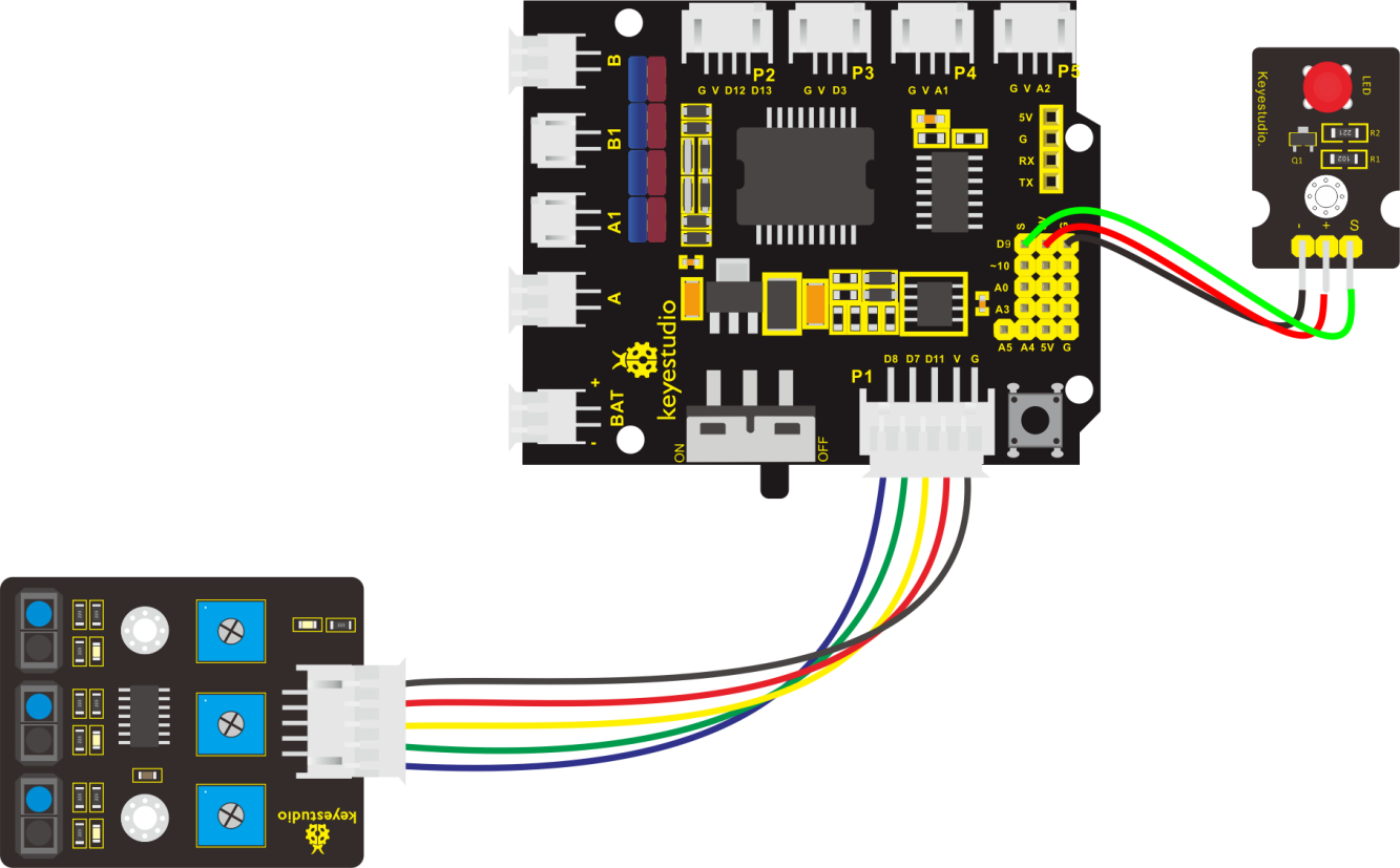
4. Connection Diagram
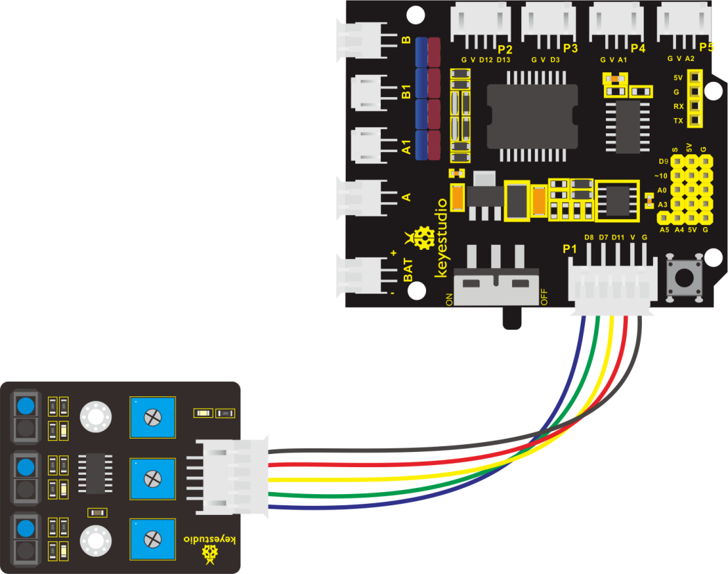
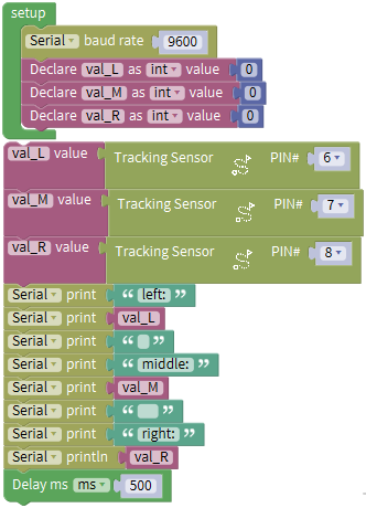
5. Test Code
The program will be generated if you find the following file and drag it into Mixly software.
File type |
Route |
File Name |
|---|---|---|
MIX File |
../tutorial for Mixly/Mixly Code/ lesson_3_Line Tracking Sensor |
lesson_3.1_Line Tracking Sensor |
You could edit code step by step as follows:
Click “Control” to get block
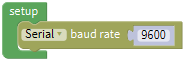
Enter “Serial port” to move block
 into block.
Go to “Variables” to move
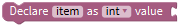 into blockfor three times;then enter “Math” to drag block
  and copy it for 3 times.
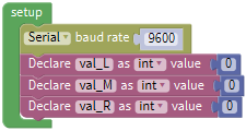
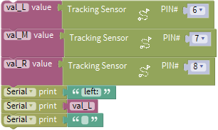
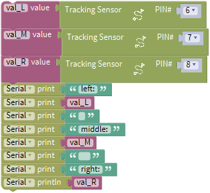
Combine
with block, and separately set to val_L, val_M and val_R.
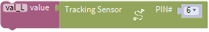
Enter “Variables” to move out block
 ,
,Go to “Sensor” → “DigitalRead” →
Integrate block
with block.The line tracking sensor is linked with D6, so set to PIN 11
 .
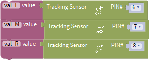
.Replicate block
 twice,and separately change val_L into val_M and val_R;
The tracking sensor is also connected to D7 and D8, therefore, set to PIN 7 and PIN 8
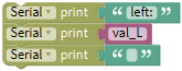
Click “Serial Port”to drag out block
 ,and go to “Text” to move block
 into block,
Change hello into left:
+=
Copy block
again,and enter“Variables”to move block into
intoReplicate code
once and delete left:, as shown below:
Duplicate code string
 once,and change left:into middle : , val_L into val_M.
Copy block
 ,and alter left:into right:
Go to“Serial Port”to drag out
 block ,and enter “Variables” to drag
  into block.
Enter “Control” to get block
, and delay in 500ms.
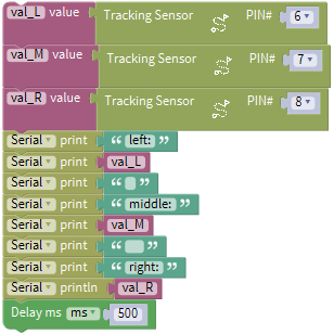
Complete Program
6. Test Result
Upload the code on development board, open serial monitor to check line tracking sensors. And the displayed value is 1(high level) when no signals are received.
The value becomes into 0 when covering sensor with paper.
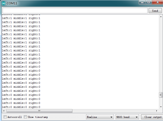
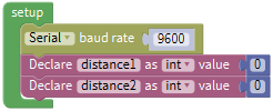
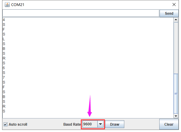
7. Code explanation
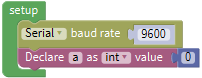
Serial.begin(9600)-initialize and set baud rate to 9600
pinMode- decide if the pin mode of micron controller is input or output.
digitalRead- read the status of pin(HIGH, LOW)
8. Extension Practice
After knowing its working principle, connect an LED to D3. We could control LED by line tracking sensor.
The program will be generated if you find the following file and drag it into Mixly software.
File type |
Route |
|---|---|
MIX File |
../tutorial for Mixly/Mixly Code/ lesson_3_Line Tracking Sensor |
File Name |
|
lesson_3.2_Extension Practice |
You could edit code step by step as follows:
Click “Control” to get block
Enter “Serial Port” to move block
into
+ =
Go to “Variables” to drag out block
and copy it twiceSeparately change item into val_L, val_M and val_R.
Go to “Math” to move out block
and replicate it twice.
Edit code string as follows:
Go to “Variables” to drag out block
,Then click “Sensor” → “DigitalRead” →
Move block
into block,The line tracking sensor is linked with D6, so set to PIN 11.
Replicate block
twice,and separately change val_L into val_M and val_R;The tracking sensor is also connected to D7 and D8, therefore, set to PIN 7 and PIN 8.
Click “Serial Port” to drag out block
,and go to “Text” to move blockinto block,Change hello into left:
+ =Copy block
again,and enter“Variables”to move blockinto .Replicate code
once and delete left:, as shown below:
Duplicate code string
once,and change left:into middle : , val_L into val_M.Copy block
,and alter left:into right:Go to“Serial Port”to drag out
block ,and enter “Variables” to drag into block.
Enter“Control”to move out block
 , click
 to move block
 into
into block, thenblock turns into
 .
.Go to “Logic” to move block
 into if block.
Enter “Variables” to drag block
into the left box of block“=”,click “Math” to move blockinto right box of“=”,and change 0 into 1.
Go to “sensor” → “ControlOutput” →
Place it into do block,and set to LOW
LED is linked with D3,therefore, set to PIN 9.
Copy block
 again and keep it into else
Then set to HIGH, click ”Control” to move out block
,and delay in 2000ms.
Replicate code string
 twice,and respectively set to val_M and val_R.
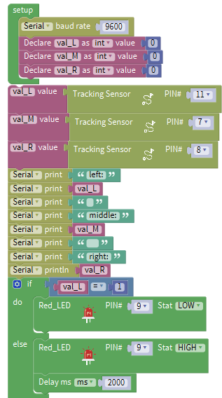
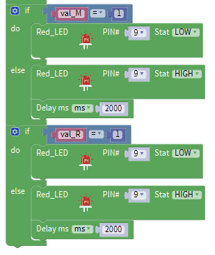
Complete Program:
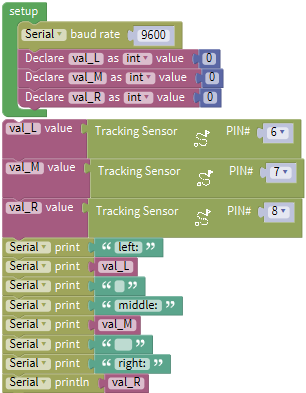
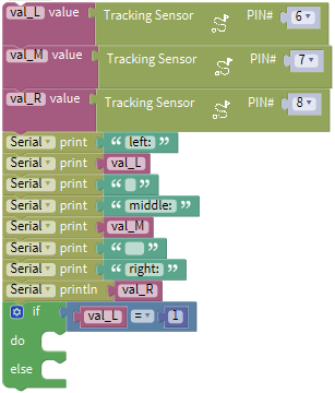
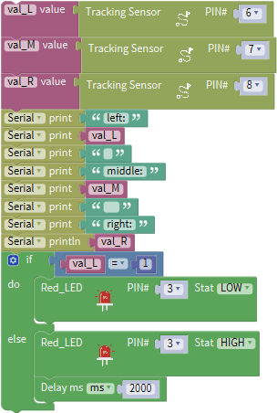
Initialization Set baud rate to 9600 Set val_L to integer 0 Set val_M to integer 0 Set val_R to integer 0. Set the digital signals read by left TCRT5000 IR tube to val_L Set the digital signals read by middle TCRT5000 IR tube to val_M Set the digital signals read by right TCRT5000 IR tube to val_R
Serial port prints left: Serial port displays the digital signals read by left TCRT5000 IR tube.
Serial port prints blank space Serial port prints middle: Serial Port shows the digital signals read by middle TCRT5000 IR tube Serial port prints blank space Serial port prints right: Serial port displays the digital signals read by right TCRT5000 IR tube If the digital signal read by right TCRT5000 IR tube is 1, the program under do block will be executed.
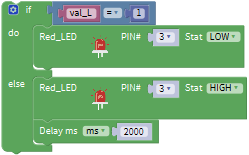
Turn off red LED If the digital signal read by left TCRT5000 IR tube is not 1, the program under else block will be executed. Light up red LED Delay in 2000ms If the digital signal read by middle TCRT5000 IR tube is 1, the program under do block will be executed.
Turn off red LED If the condition of digital signal read by left TCRT5000 IR tube=1 is not met, the program under else block will be executed. Delay in 2000ms If the condition of digital signal read by right TCRT5000 IR tube=1 is met, the program under do block will be executed. LED Turn off red LED If the condition of digital signal read by middle TCRT5000 IR tube=1 is not met, the program under else block will be executed. Light up red LED Delay in 2000ms.
Upload the code to development board, we could see LED light up when covering the line tracking sensor by hand.
Project 4: Servo Control
1. Description
Servo motor is a position control rotary actuator. It mainly consists of housing, circuit board, core-less motor, gear and position sensor. Its working principle is that the servo receives the signal sent by MCU or receiver and produces a reference signal with a period of 20ms and width of 1.5ms, then compares the acquired DC bias voltage to the voltage of the potentiometer and obtain the voltage difference output.
When the motor speed is constant, the potentiometer is driven to rotate through the cascade reduction gear, which leads that the voltage difference is 0, and the motor stops rotating. Generally, the angle range of servo rotation is 0° –180 °
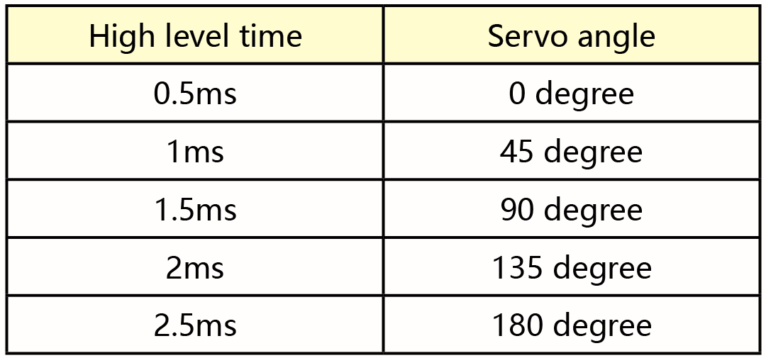
The rotation angle of servo motor is controlled by regulating the duty cycle of PWM (Pulse-Width Modulation) signal. The standard cycle of PWM signal is 20ms (50Hz). Theoretically, the width is distributed between 1ms-2ms, but in fact, it’s between 0.5ms-2.5ms. The width corresponds the rotation angle from 0° to 180°. But note that for different brand motor, the same signal may have different rotation angle.
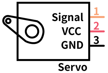
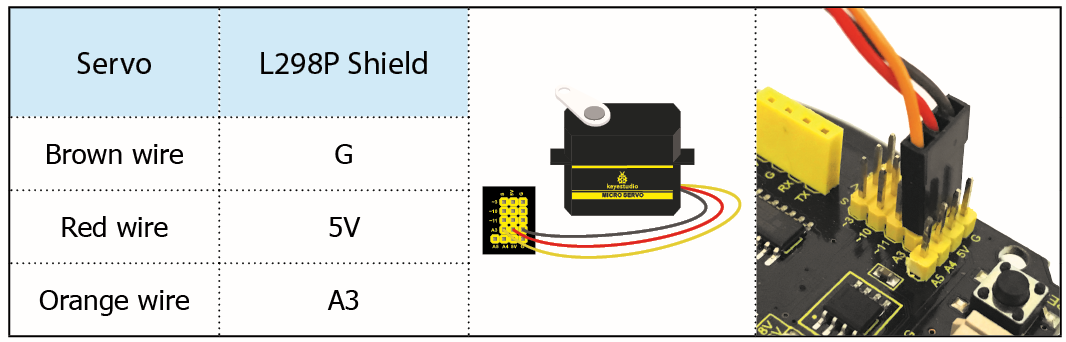
In general, servo has three line in brown, red and orange. Brown wire is grounded, red one is positive pole line and orange one is signal line.
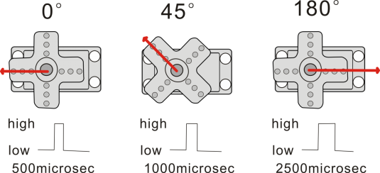
The corresponding servo angles are shown below:
2. Specification
Working voltage: DC 4.8V ~ 6V
Operating angle range: about 180 ° (at 500 → 2500 μsec)
Pulse width range: 500 → 2500 μsec
No-load speed: 0.12 ± 0.01 sec / 60 (DC 4.8V) 0.1 ± 0.01 sec / 60 (DC 6V)
No-load current: 200 ± 20mA (DC 4.8V) 220 ± 20mA (DC 6V)
Stopping torque: 1.3 ± 0.01kg · cm (DC 4.8V) 1.5 ± 0.1kg · cm (DC 6V)
Stop current: ≦ 850mA (DC 4.8V) ≦ 1000mA (DC 6V)
Standby current: 3 ± 1mA (DC 4.8V) 4 ± 1mA (DC 6V)
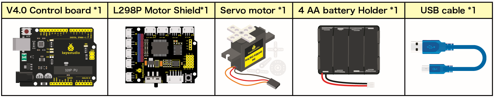
3. Components
4. Wiring Diagram
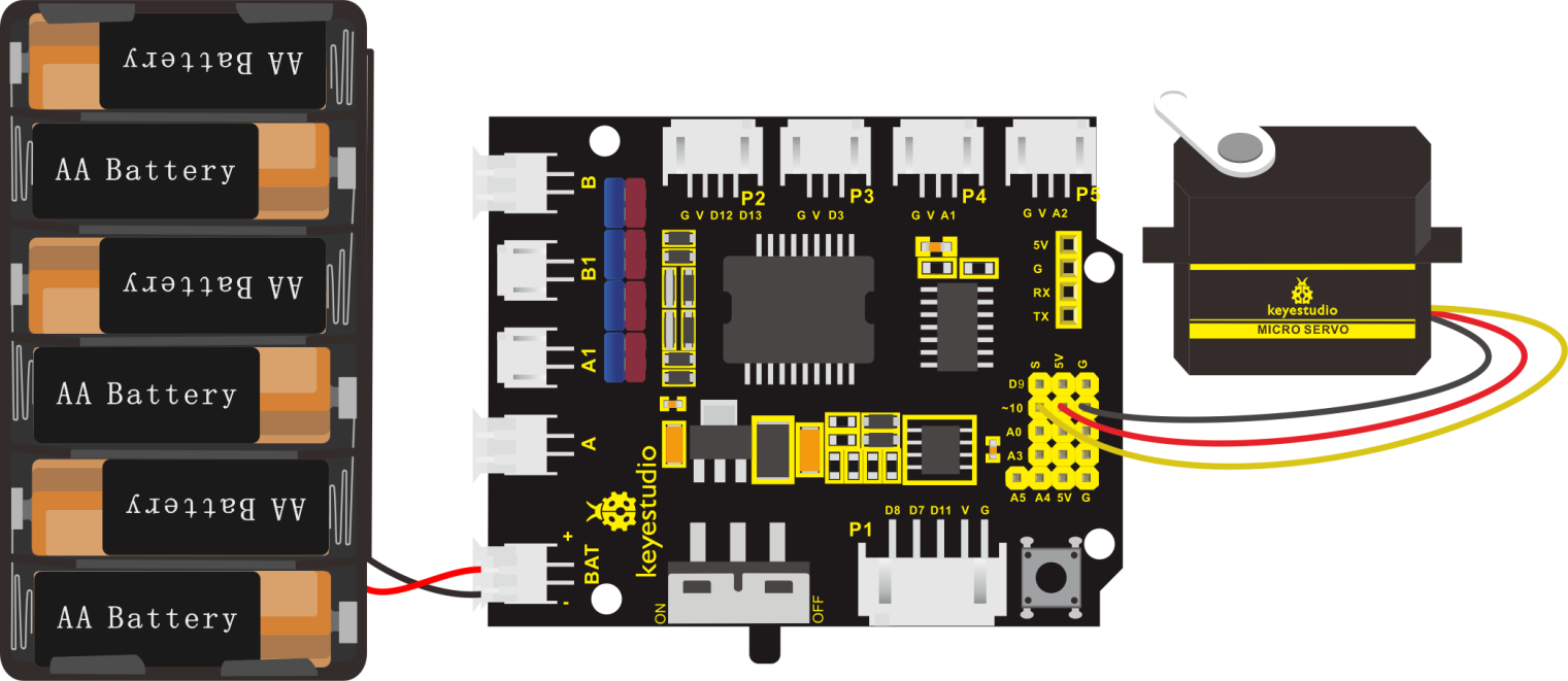
Wiring note: the brown line of servo is linked with Gnd(G), the red line is connected to 5v(V) and orange line is attached to digital 10.
The servo has to be connected to external power due to its high demand for driving servo current. Generally, the current of development board is not enough. If without connected power, the development board could be burnt.
5. Test Code
The program will be generated if you find the following file and drag it into Mixly software.
File type |
Route |
File Name |
|---|---|---|
MIX File |
../tutorial for Mixly/Mixly Code/ lesson_4_Servo Control |
lesson_4_Servo Control |
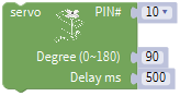
You could edit code step by step as follows:
Go to“Control”to get block
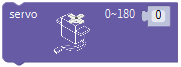
Enter“Module”→“Drive_Module”to get block
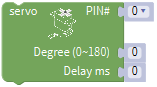 and place it into block,
The servo is linked with D10, so set to PIN 10.
Set servo to 90°,and delay in 500ms.
Replicate code string
 for three times,respectively change 90 into 0, 180 and 0.
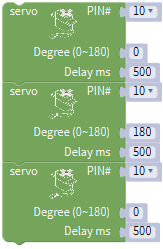
Complete Program:
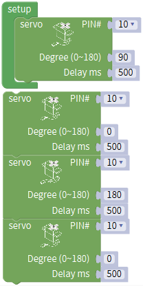
Upload code successfully and power on, servo swings in the range of 0° to 180°.
Project 5: Ultrasonic Sensor
1. Description
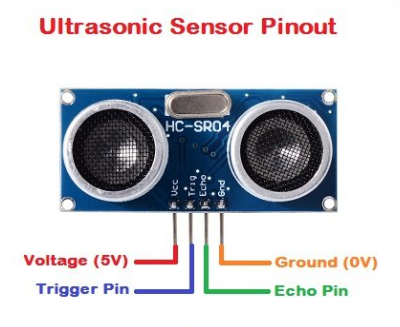
The HC-SR04 ultrasonic sensor uses sonar to determine distance to an object like bats do. It offers excellent non-contact range detection with high accuracy and stable readings in an easy-to-use package. It comes complete with ultrasonic transmitter and receiver modules.
The HC-SR04 or the ultrasonic sensor is being used in a wide range of electronics projects for creating obstacle detection and distance measuring application as well as various other applications. Here we have brought the simple method to measure the distance with Arduino and ultrasonic sensor and how to use ultrasonic sensor wit h Arduino.
2. Specification
Power Supply :+5V DC
Quiescent Current : <2mA
Working Current: 15mA
Effectual Angle: <15°
Ranging Distance : 2cm – 400 cm
Resolution : 0.3 cm
Measuring Angle: 30 degree
Trigger Input Pulse width: 10uS
3. Components

4. The principle of ultrasonic sensor
As the above picture shown, it is like two eyes. One is transmitting end, the other is receiving end.
The ultrasonic module will emit the ultrasonic waves after trigger signal. When the ultrasonic waves encounter the object and are reflected back, the module outputs an echo signal, so it can determine the distance of object from the time difference between trigger signal and echo signal.
The t is the time that emitting signal meets obstacle and returns, and the propagation speed of sound in the air is about 343m/s, therefore, distance = speed * time, because the ultrasonic wave emits and comes back, which is 2 times of distance, so it needs to be divided by 2, the distance measured by ultrasonic wave = (speed * time)/2
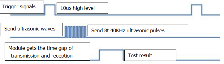
Use method and timing chart of ultrasonic module:
Setting the delay time of Trig pin of SR04 to 10μs at least, which can trigger it to detect distance.
2. After triggering, the module will automatically send eight 40KHz ultrasonic pulses and detect whether there is a signal return. This step will be completed automatically by the module.
3. If the signal returns, the Echo pin will output a high level, and the duration of the high level is the time from the transmission of the ultrasonic wave to the return.
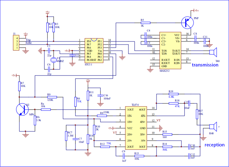
Circuit diagram of ultrasonic sensor:
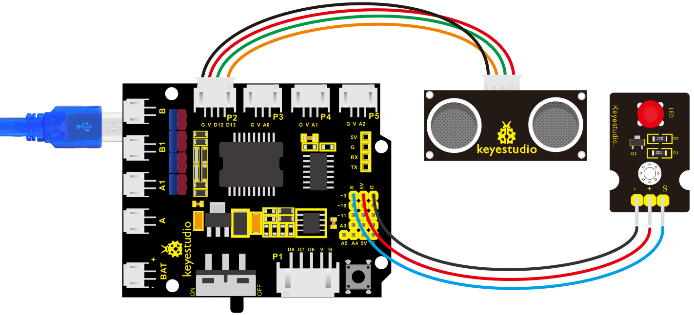
5. Connection Diagram
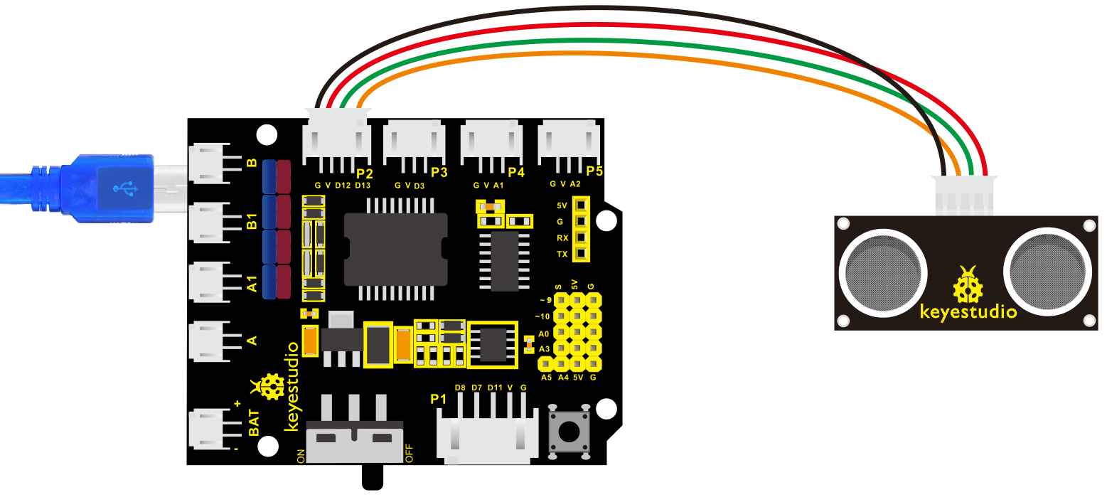
Wiring guide:
Ultrasonic sensor keyestudio V5 sensor shield
VCC → 5v(V)
Trig → 12(S)
Echo → 13(S)
Gnd → Gnd(G)
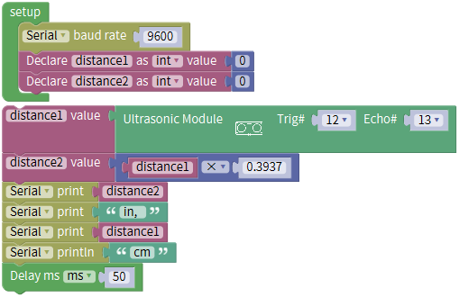
6. Test Code
The program will be generated if you find the following file and drag it into Mixly software.
File type |
Route |
File Name |
|---|---|---|
MIX File |
../tutorial for Mixly/Mixly Code/lesson_5_Ultrasonic Sensor |
lesson_5.1_Ultrasonic Sensor |
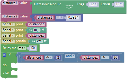
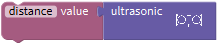
You could edit code step by step as follows:
Click“Control”module to get block
.Enter“Serial Port”to move block
into block.
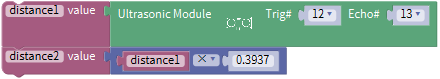
Go to“Variables” to get block
and copy it twice. Respectively change item into distance 1 and distance 2.Click“Math” to move out block
and replicate it twice.
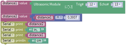
Click “Variables” to drag out block
 ,and enter “sensor” → “OtherSensor” →.
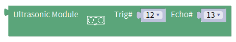
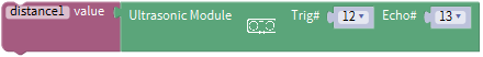
Combine block
with block ,Trig pin of ultrasonic sensor is connected to D12(S) of shield,Echo is attached to D13(S),so set Trig 12 and Echo 13.
Click“Variables”to get block
 ,and drag out
 from“Math” and keep it behind block.
Go to“Variables” to move out block
 left 1 box“.
Then change another 1 into 0.3937,and set to“×”.
Go to“Serial Port ” to drag out block
 ,and click “Variables” to get block
 .
.Combine
with
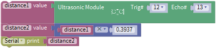
Go to “Serial Port” to get block
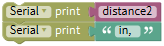
,then click “Text” module to drag block into ,and change hello into in.
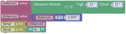
Copy code string
 once,change distance2 into distance1,in into cm
Click“Control”to get block
,delay in 50ms.
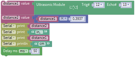
Click“Control”to get block
,delay in 50ms.
Complete Program:
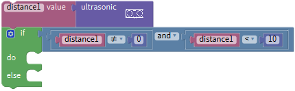
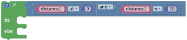
7. Extension Practice
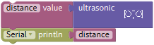
We have measured the distance displayed by ultrasonic sensor. How about controlling the LED with the measured distance? Let’s try it, connect an LED light module to the D3 pin.
The program will be generated if you find the following file and drag it into Mixly software.
File type |
Route |
|---|---|
MIX File |
../tutorial for Mixly/Mixly Code/lesson_5_Ultrasonic Sensor |
File Name |
|
lesson_5.2_Extension Practice |
You could edit code step by step as follows:
Enter“Control” to get block
Click“Serial Port” to drag out block
into
Go to“Variables” to move out block
and copy it twice.Enter“Math” to drag out block
and replicate twice, and change item into distance 1 and distance 2.Edit the code string as follows:
Go to “Variables” to move out
block,then click“sensor”→“OtherSensor” →Combine it with block
,the pin Trig of ultrasonic sensor is linked with D12(S) of expansion board, pin Echo is attached to D13(S); therefore, click the triangle button to select 12 and 13.
Click“Variables” to get block
,and drag out from “Math” and keep it behind block.Go to“Variables” to move out block
left 1 box“. Then change another 1 into 0.3937,and set to “×”.
Go to “Serial Port ” to drag out block
,and click “Variables” to get block.Combine
with
Go to “Serial Port” to get block
,then click “Text” moduleto drag blockinto,and change hello into in.
Replicate code string
once,and change distance2 into distance1,and in into cm.Go to“Control”to move out block
and delay in 50ms
Click“Control” and drag it into block
 , clickand move
 into
into  then we get block
 .
.Go to “Logic” to get
 and .
and .Place
into if block,and leave in the left box of block.Enter“Variables” to get block
and keep it at left box of block “=”.Go to “Math” to move out
into right box of block “=”,and change 0 into 2, “=” into “≥”.Replicate block
 once and set
Go to“Control”to move out block
and delay in 50ms
Click“Control”and drag it into block
,clickand moveintothen we get block.Go to “Logic” to get
and .Place
into if block,and leave in the left box of block.Enter “Variables” to get block
and keep it at left box of block“=”.Go to“Math” to move out
into right box of block “=”,and change 0 into 2, “=”into“≥”.Replicate block
once and set Click “sensor” →“ControlOutput”→
and place it into do block,The S end of LED Module is connected to D3 of expansion board,therefore,click the triangle button to select 3.
 Replicate block
 once and leave it into “else” and set to LOW.
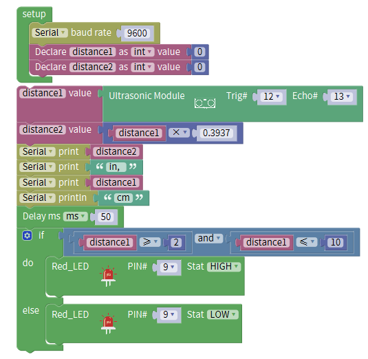
Complete Program:
Upload test code to development board and block ultrasonic sensor by hand, then check if LED is on
8. Test Result
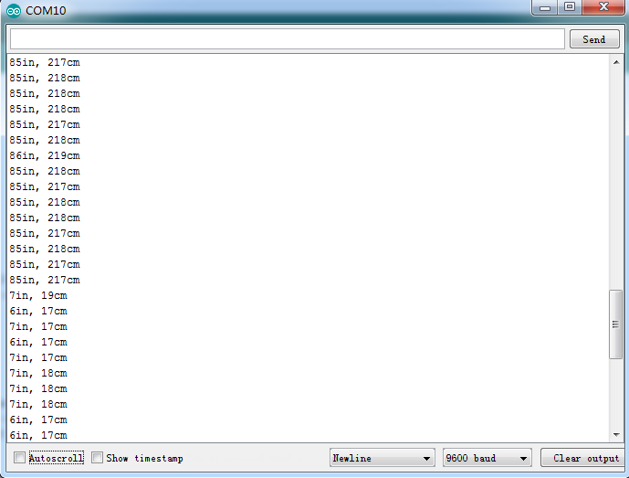
Upload test code on the development board, open serial monitor and set baud rate to 9600. The detected distance will be displayed, the unit is cm and inch. Hinder the ultrasonic sensor by hand, the displayed distance value gets smaller.
Project 6: IR Reception
1. Description
There is no doubt that infrared remote control is ubiquitous in daily life. It is used to control various household appliances, such as TVs, stereos, video recorders and satellite signal receivers. Infrared remote control is composed of infrared transmitting and infrared receiving systems, that is, an infrared remote control and infrared receiving module and a single-chip microcomputer capable of decoding.
The 38K infrared carrier signal emitted by remote controller is encoded by the encoding chip in the remote controller. It is composed of a section of pilot code, user code, user inverse code, data code, and data inverse code. The time interval of the pulse is used to distinguish whether it is a 0 or 1 signal and the encoding is made up of these 0, 1 signals.
The user code of the same remote control is unchanged. The data code can distinguish the key.
When the remote control button is pressed, the remote control sends out an infrared carrier signal. When the IR receiver receives the signal, the program will decode the carrier signal and determines which key is pressed. The MCU decodes the received 01 signal, thereby judging what key is pressed by the remote control.
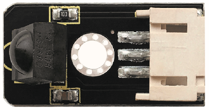
Infrared receiver we use is an infrared receiver module. Mainly composed of an infrared receiver head, it is a device that integrates reception, amplification, and demodulation. Its internal IC has completed demodulation, and can achieve from infrared reception to output and be compatible with TTL signals. Additionally, it is suitable for infrared remote control and infrared data transmission. The infrared receiving module made by the receiver has only three pins, signal line, VCC and GND. It is very convenient to communicate with arduino and other microcontrollers.
2. Specification
Operating Voltage: 3.3-5V(DC)
Interface: 3PIN
Output Signal: Digital signal
Receiving Angle: 90 degrees
Frequency: 38khz
Receiving Distance: 10m
3. Components
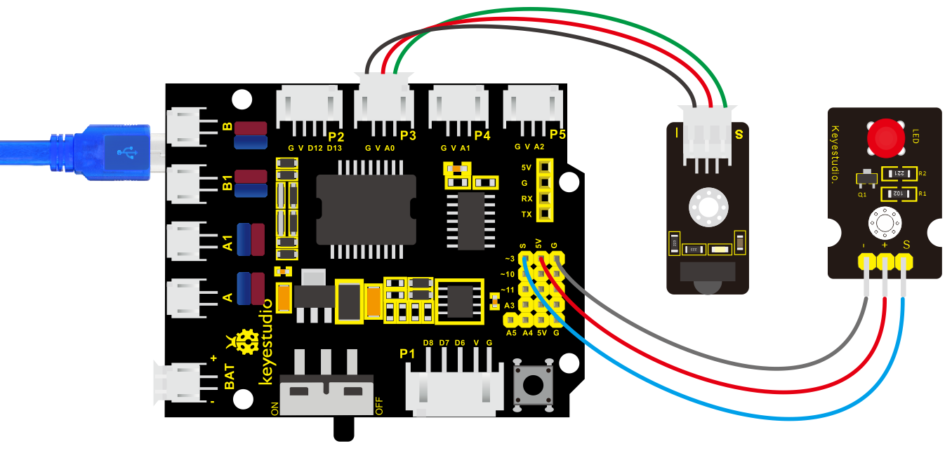
4. Connection Diagram
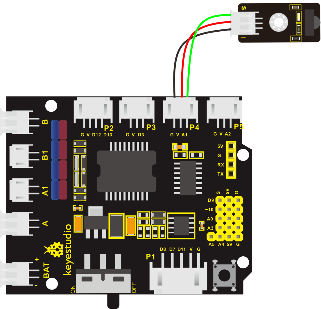
Respectively link “-”, “+” and S of IR receiver module with G(GND), V(VCC)and A0 of keyestudio development board.
Attention: On the condition that digital ports are not available, analog ports can be regarded as digital ports. A0 equals to D14, A1 is equivalent to digital 15.
5. Test Code
The program will be generated if you find the following file and drag it into Mixly software.
File type |
Route |
File Name |
|---|---|---|
MIX File |
../tutorial for Mixly/Mixly Code/ lesson_6_IR Reception |
lesson_6.1_IR Reception |
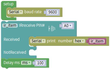
You could edit code step by step as follows:
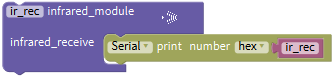
(1) Enter “Control” Module to get block.
(2) Click “Serial Port”Module to drag blockinto block.
(3) Go to “Module”→”Communicate_Module”→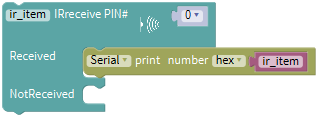 ,
,
(4) Signal end of IR receiver module is connected to A1 of shield, therefore, click triangle button to select A0.

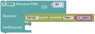
(5) Click “Control” Module,to moveout, delay in 100ms
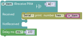
Complete Program:
6. Test Result
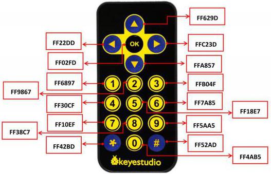
Upload test code, open serial monitor and set baud rate to 9600, point remote control to IR receiver and the corresponding value will be shown, if pressing so long, the error codes will appear.
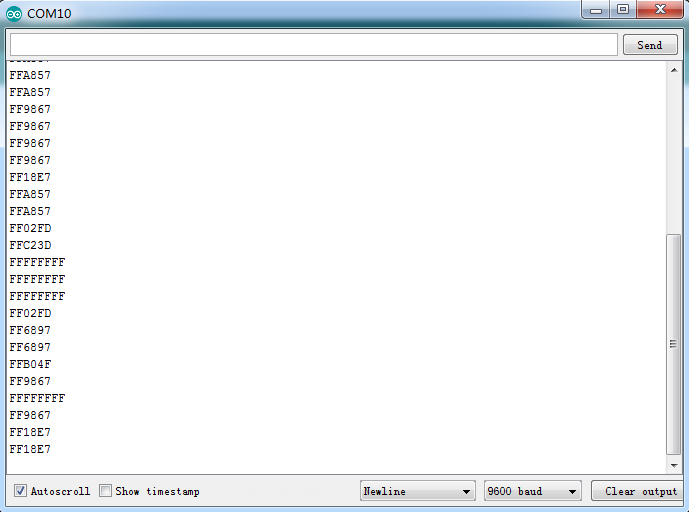
Below we have listed out each button value of keyestudio remote control. So you can keep it for reference.
7. Extension Practice:
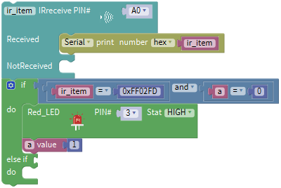
We decoded the key value of IR remote control. How about controlling LED by the measured value? We could operate an experiment to affirm. Attach an LED to D3, then press the keys of remote control to make LED light up and off.
The program will be generated if you find the following file and drag it into Mixly software.
File type |
Route |
|---|---|
MIX File |
../tutorial for Mixly/Mixly Code/ lesson_6_IR Reception |
File Name |
|
lesson_6.2_Extension Practice |
You could edit code step by step as follows:
Enter“Control”module to get block
.Go to“Serial Port”to move out block
into block.Go to ”Module”→”Communicate_Module”→
S end of IR receiver module is linked with A0. therefore, click triangle button to set A0.
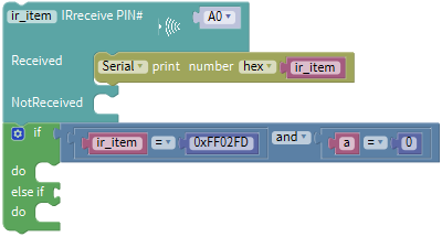
Go to “Variables” to move block
into block,Go to“Math”to drag out block
and integrate with , then change item into a.
Click “Control”module to get block
,click,move into
into  block,thenturns into
 block.
Go to “Logic”,and find out block
. Leave it behind if blockGo to“Logic” to place
in the left box.Click“Variables” to move
 in the left box of“=” block,go to“Math” to drag outinto right box of “=”,then change 0 into 0xFF02FD.
Copy
 once and keep it into right box of ”and” block,change ir_item into a,0xFF02FD into 0.
Click “sensor”→ “ControlOutput”→
Keep it into the first do block,S end of red LED module is linked with D3 of expansion board,and set to Pin 3.
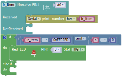
Go to“Variables”to move
 below“Red_LED…HIGH”block.
Click“Math” to get block
into,and change 0 into 1.
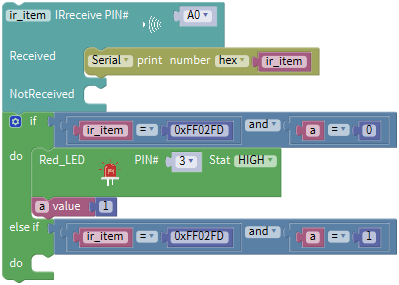
Replicate
 once and move into “else if”, change 0 into 1.
- Replicate code string
 once and place it into second do block.
 Click“HIGH”into“LOW”,1 into 0.
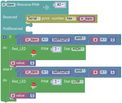
Complete Program:
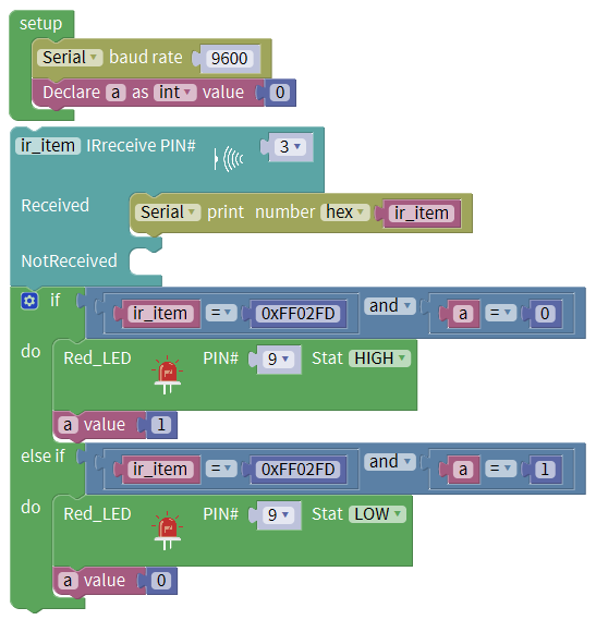
Upload code to development board, press “OK” key on remote control to make LED on and off.
Project 7: Bluetooth Remote Control
1. Description
Bluetooth, a simple wireless communication module most popular since the last few decades and easy to use are being used in most of the battery-powered devices.
Over the years, there have been many upgrades of Bluetooth standard to keep fulfil the demand of customers and technology according to the need of time and situation.
Over the few years, there are many things changed including data transmission rate, power consumption with wearable and IoT Devices and Security System.
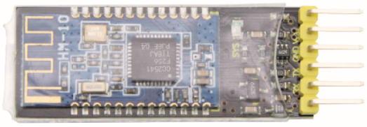
Here we are going to learn about HM-10 BLE 4.0 with Arduino Board. The HM-10 is a readily available Bluetooth 4.0 module. This module is used for establishing wireless data communication. The module is designed by using the Texas Instruments CC2540 or CC2541 Bluetooth low energy (BLE) System on Chip (SoC).
2. Parameters
Bluetooth protocol: Bluetooth Specification V4.0 BLE
No byte limit in serial port Transceiving
In open environment, realize 100m ultra-distance communication with iphone4s
Working frequency: 2.4GHz ISM band
Modulation method: GFSK(Gaussian Frequency Shift Keying)
Transmission power: -23dbm, -6dbm, 0dbm, 6dbm, can be modified by AT command.
Sensitivity: ≤-84dBm at 0.1% BER
Transmission rate: Asynchronous: 6K bytes ; Synchronous: 6k Bytes
Security feature: Authentication and encryption
Supporting service: Central & Peripheral UUID FFE0, FFE1
Power consumption: Auto sleep mode, stand by current 400uA~800uA, 8.5mA during transmission.
Power supply: 5V DC
Working temperature: –5 to +65 Centigrade
3. Components
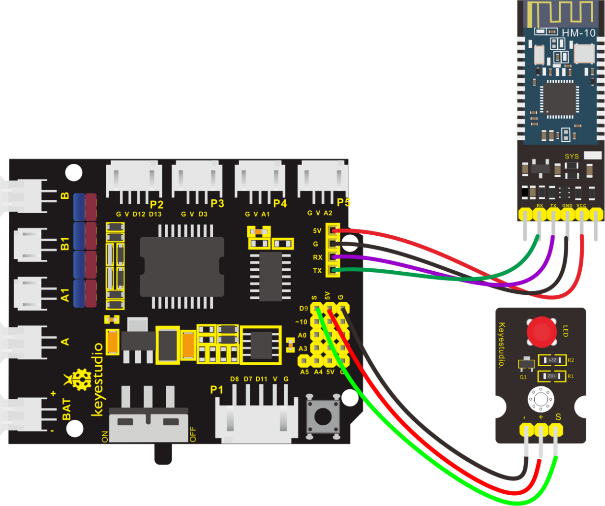
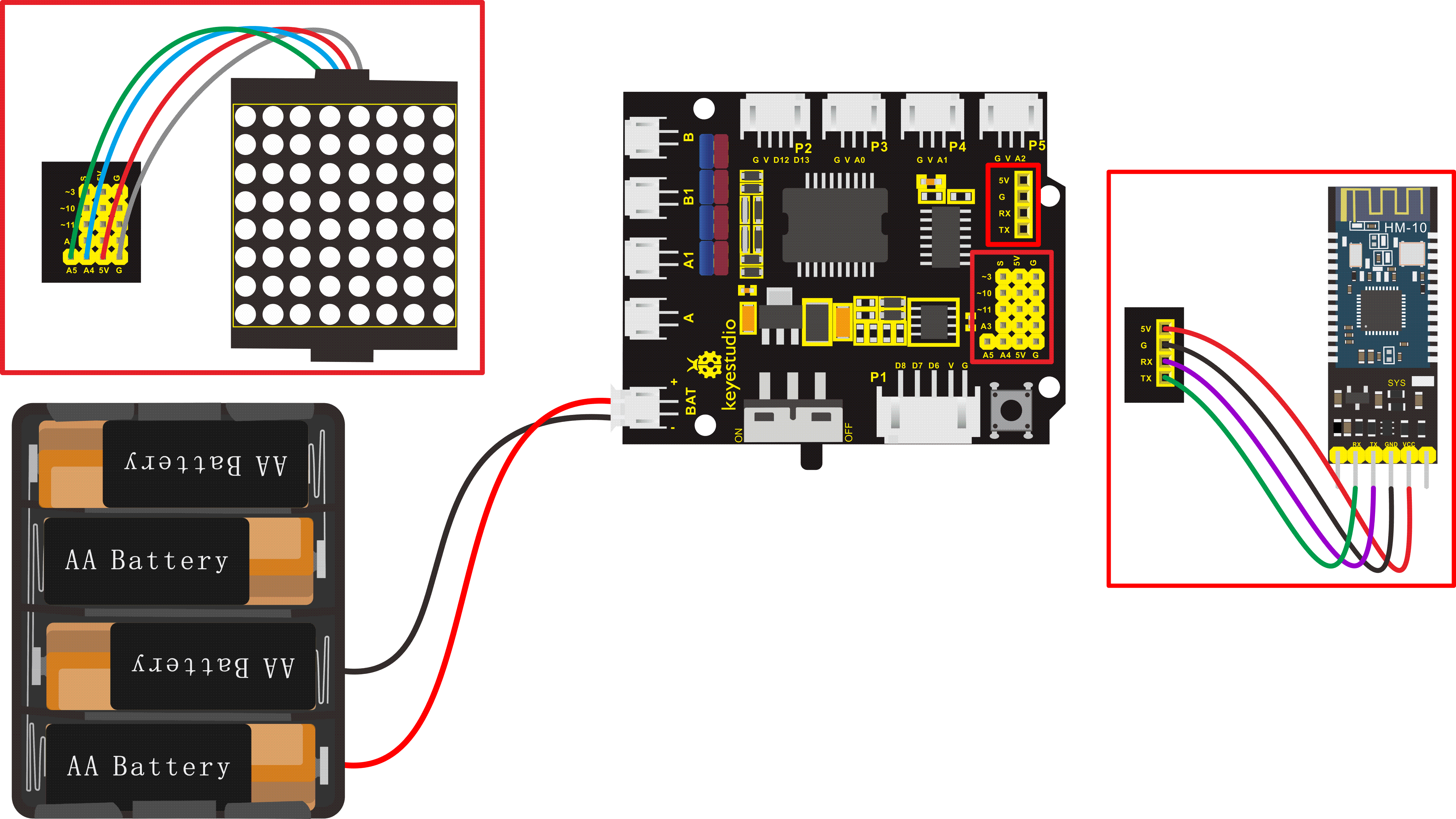
4. Wiring Diagram
5. Test Code
The program will be generated if you find the following file and drag it into Mixly software.
File type |
Route |
File Name |
|---|---|---|
MIX File |
../tutorial for Mixly/Mixly Code/lesson_7_Bluetooth Remote Control |
lesson_7.1_Bluetooth Remote Control |
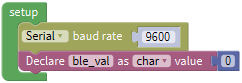
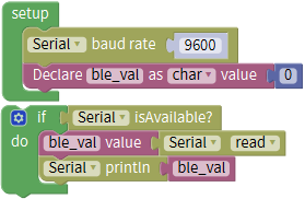
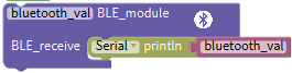
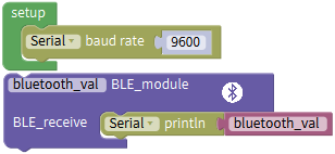
You could edit code step by step as follows:
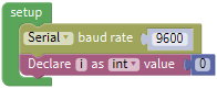
Click “Control”to get block
Enter “Serial Port”to move block
into
+=
Click “Variables” to drag out
into, enter“Math” block to get block .Place it behind “value”,and change item into ble_val,click the drop-down triangle button to select char.
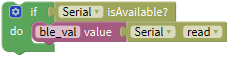
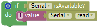
Go to “Control” to get block
,and click “Serial Port” to move out block into if block.

Enter “Variables” to drag out block
 into do block,click “Serial Port” to move out block
  into block.
Enter “Serial Port” to move block
 into do block,then click “Variables” to drag out
  into block.
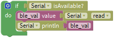
Complete Program:
(There will be contradiction between serial communication of code and communication of Bluetooth when uploading code, therefore, don’t link with Bluetooth module before uploading code.)
After uploading code on development board, then insert Bluetooth module, wait for the command from cellphone.
6. Download the APP
The code is the received signal by serial monitor, in this project, we send signal to control robot car via cellphone.
Then we need to download the APP.
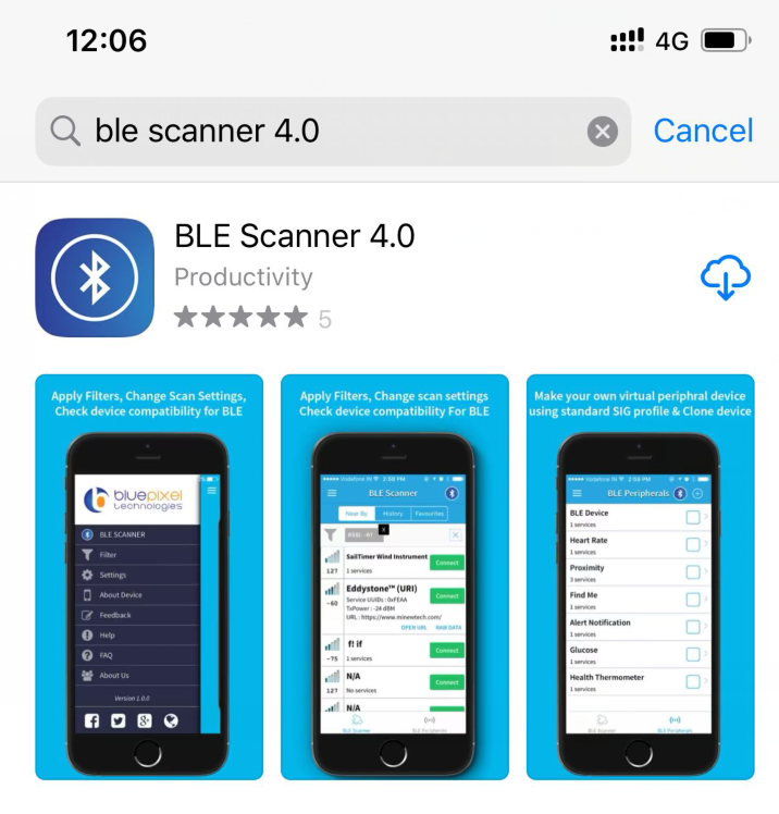
iOS system
Note: Allow APP to access “location” in settings of your cellphone when connecting to Bluetooth module, otherwise, Bluetooth may not be connected.
Enter APP STORE to search BLE Scanner 4.0, then download it.
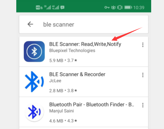
Android system
Enter Google Play to find out BLE Scanner and download.
(Enable“location”in settings of your cellphone, otherwise, app may not be searched.)
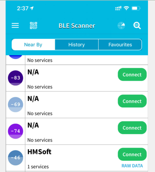
After installation, open App and enable“Location and Bluetooth” permission. Open App, the name of Bluetooth module is HMSoft. Then click “connect” to link with Bluetooth
After connecting to HMSoft, click it to get multiple options, such as device information, access permission, general and custom service. Choose “CUSTOM SERVICE”
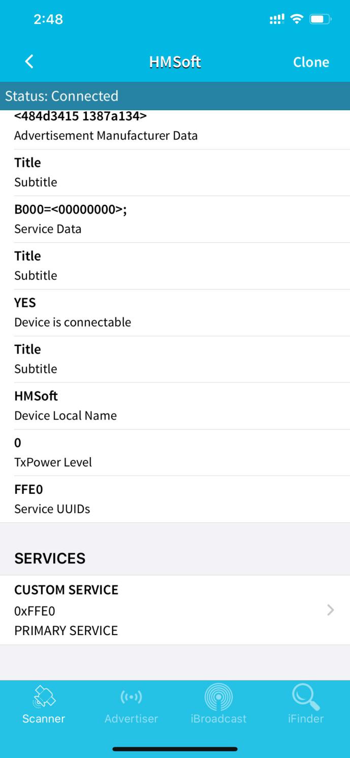
Then pop up the following page.
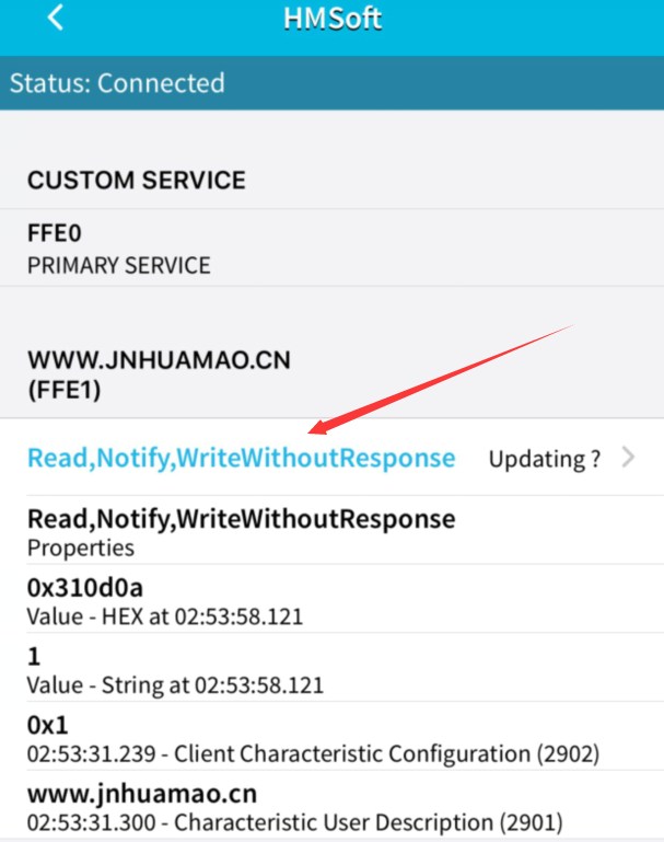
Click(Read,Notify,WriteWithoutResponse)to enter the following page
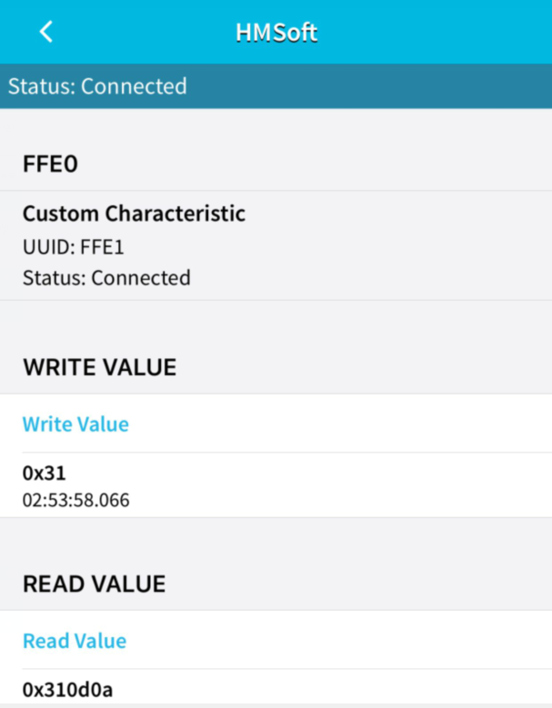
Click Write Value to enter HEX or Text.
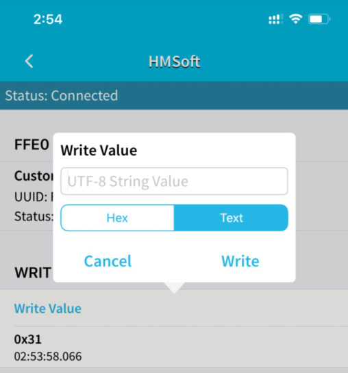
Open the serial monitor on Arduino,enter a 0 or other character on Text interface.
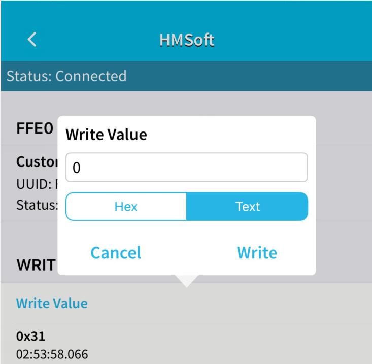
Then click “Write”, open serial monitor to view if there is a “0” signal

7.Extension Practice
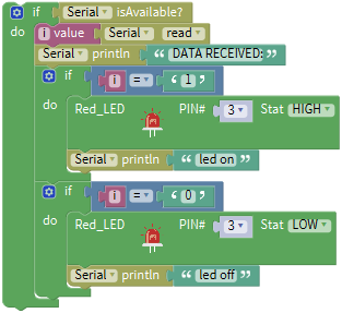
We could send a command via Bluetooth to turn on and off a LED. D3 is connected to a LED, as shown below:
The program will be generated if you find the following file and drag it into Mixly software.
File type |
Route |
|---|---|
MIX File |
../tutorial for Mixly/Mixly Code/lesson_7_Bluetooth Remote Control |
File Name |
|
lesson_7.2_Extension Practice |
You could edit code step by step as follows:
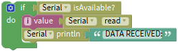
Click“Control” to get block
Enter“Serial Port”to move block
intoClick“Variables” to move block
into block,then go to “Math” to find out,Combine
with and change item into i.
Click “Control” to get block
,and enter “Serial port”to moveinto if block.
Go to“Variables”to drag block
 into do block,
Enter “Serial port”to move out
block and edit code string as follows:
Enter“Serial port” to drag out
,Click“Text”to move out
 into block,and change “hello”into DATA RECEIVED:.
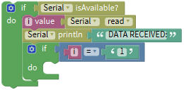
Click“Control”to move out block
into do,click “Logic” to move block into if,
Enter “Variables” to move
 into left box of “=”,then enter “Text” to get block
 and leave it into right box“=”,change a into 1.
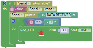
Enter“Sensor”→“ControlOutput”→
Drag it into the second do block,S end of red LED is connected to D3, therefore, set to Pin 3.
Replicate
 once and place it into the second do block. Change DATA RECEIVED:into led on.
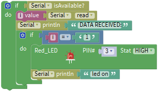
Copy code string
 once and change 1 into 0,click “HIGH” to select “LOW”,and change led on into led off.
Complete Program:
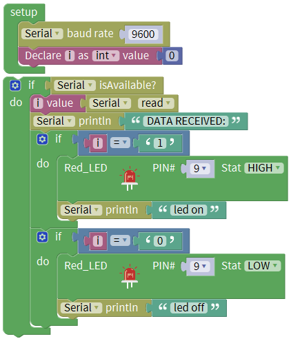
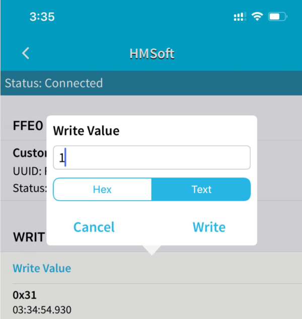
Click “Write” on APP, when you enter 1, LED will be on, when you input 0, LED will be off. (Remember to remove the Bluetooth module after finishing experiment, otherwise, burning code will be affected)
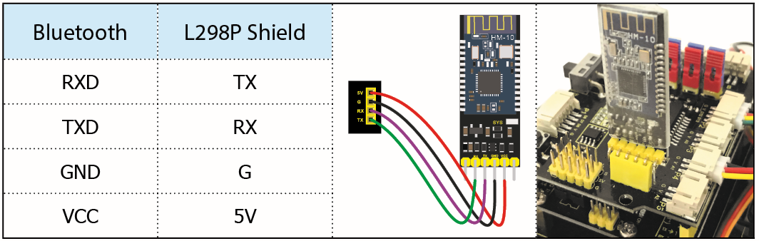
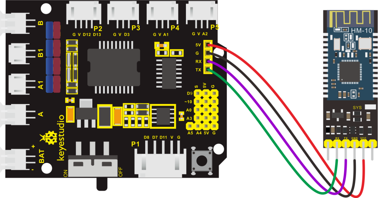
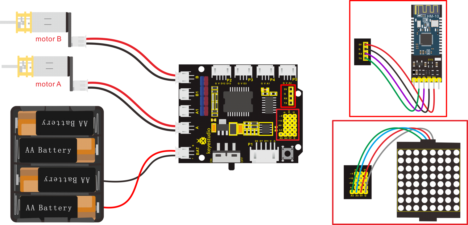
Hook-up diagram
1. STATE: state test pins, connected to internal LED, generally keep it unconnected.
2. RXD: serial interface, receiving terminal.
3. TXD: serial interface, transmitting terminal.
4. GND: Ground.
5. VCC: positive pole of the power source.
6. EN/BRK: break connect, it means breaking the Bluetooth connection, generally, keep it unconnected.
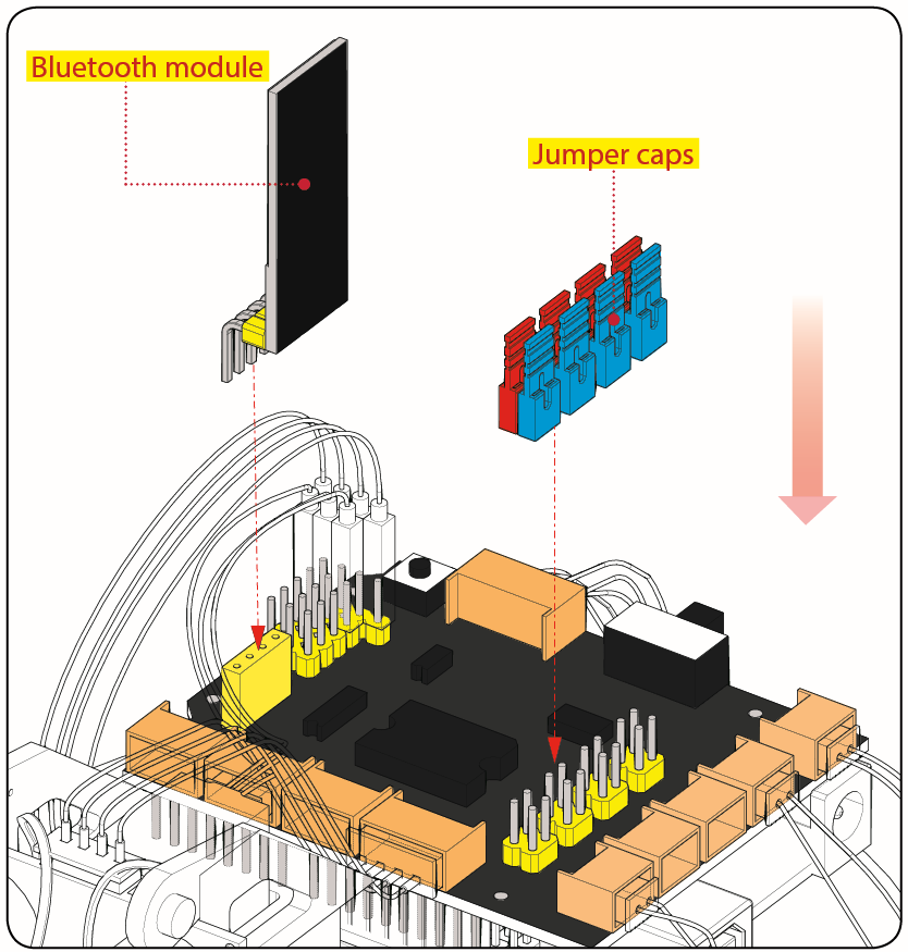
Pay attention to the pin direction when inserting Bluetooth module, and don’t insert it before uploading test code
Project 8: Motor Driving and Speed Control
1. Description
There are many ways to drive the motor. Our robot car uses the most commonly used L298P solution. L298P is an excellent high-power motor driver IC produced by STMicroelectronics. It can directly drive DC motors, two-phase and four-phase stepping motors. The driving current up to 2A, and output terminal of motor adopts eight high-speed Schottky diodes as protection.
We designed a shield based on the circuit of L298p.
The stacked design reduces the technical difficulty of using and driving the motor.
2. Specification
Logic part input voltage: DC5V
Driving part input voltage: DC 7-12V
Logic part working current: <36mA
Driving part working current: <2A
Maximum power dissipation: 25W (T=75℃)
Working temperature: -25℃~+130℃
Control signal input level: high level 2.3V<Vin<5V, low level -0.3V<Vin<1.5V
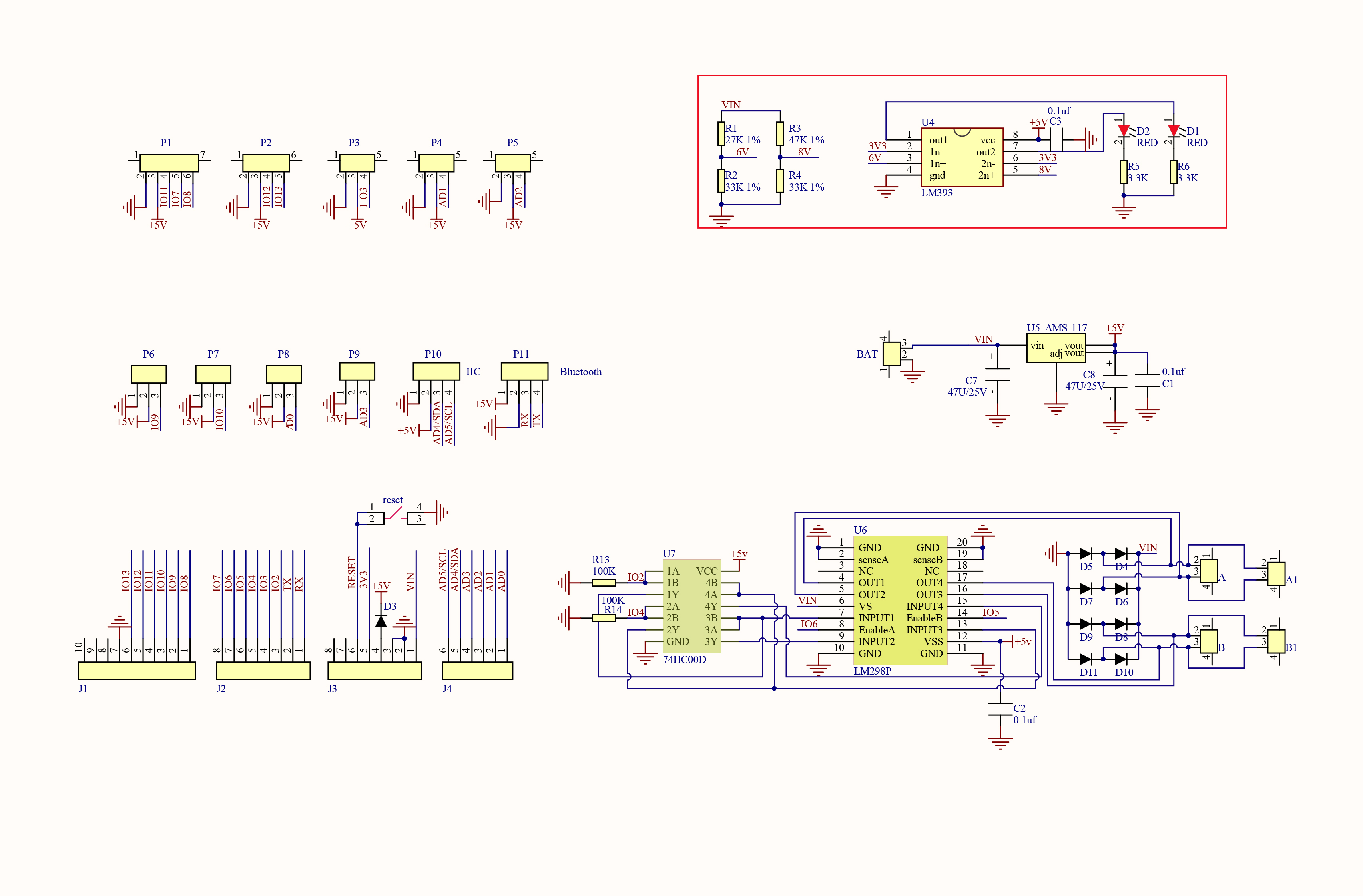
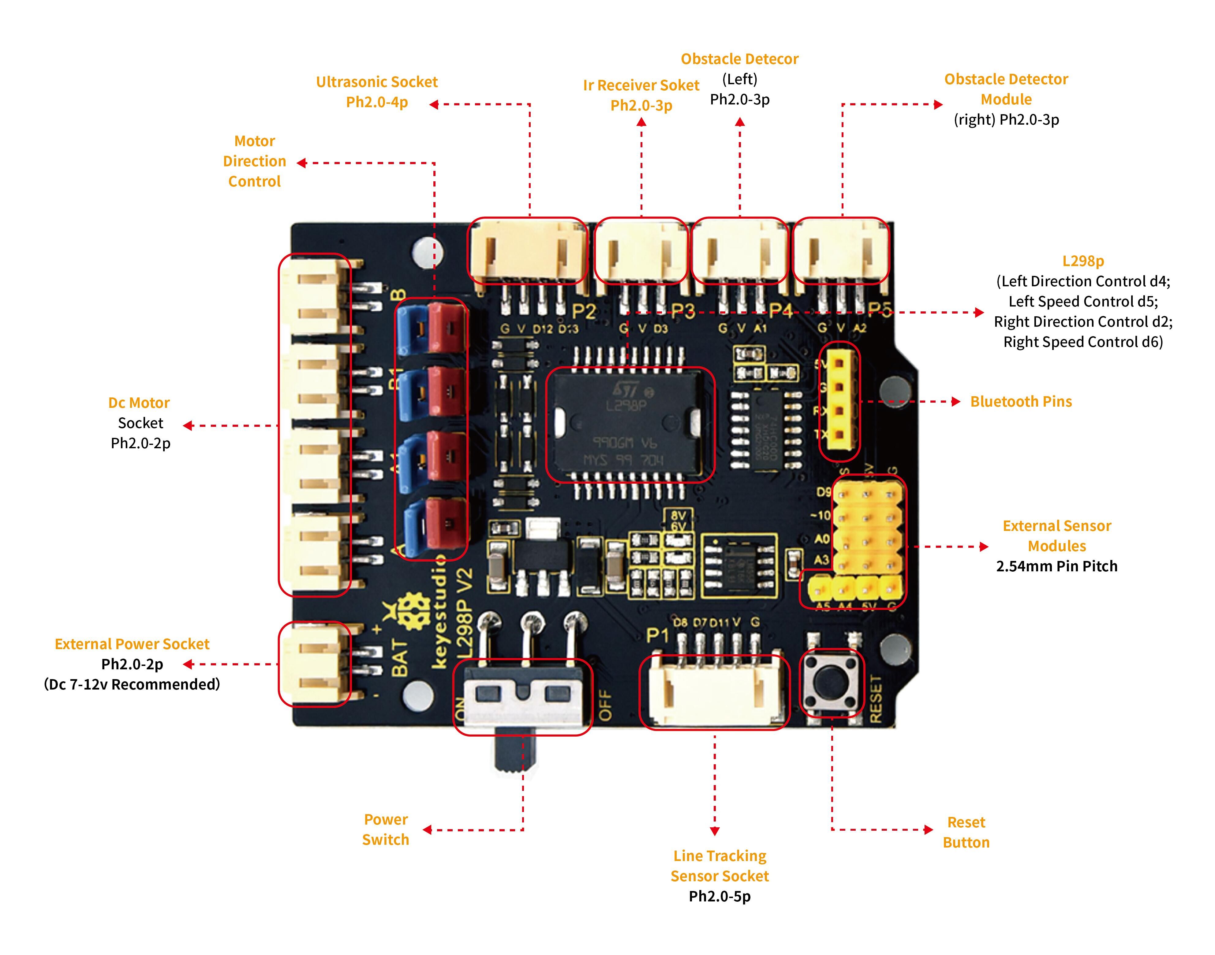
3. Drive Robot to Move
Through the above diagram, the direction pin of B motor is D4, and speed pin is D5; D2 is the direction pin of A motor, D9 is speed pin.
PWM decides 2 motors to rotate so as to drive robot car. The PWM value is in the range of 0-255, the larger the number, the faster the motor rotates.
D2 |
D6 (PWM) |
Motor(A) |
|
|---|---|---|---|
Go forward |
LOW |
200 |
Rotate clockwise |
Go back |
HIGH |
200 |
Rotate anticlockwise |
Rotate to left |
HIGH |
200 |
Rotate anticlockwise |
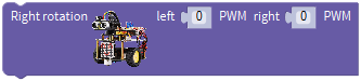
Rotate to right |
LOW |
200 |
Rotate clockwise |
Stop |
/ |
0 |
Stop |
Go forward |
D4 |
D5 PWM |
Motor(B) |
Go back |
LOW |
200 |
Rotate clockwise |
Rotate to left |
HIGH |
200 |
Rotate anticlockwise |
Rotate to right |
LOW |
200 |
Rotate clockwise |
Stop |
HIGH |
200 |
Rotate anticlockwise |
Go forward |
/ |
0 |
Stop |
Go back |
D4 |
D5 PWM |
Motor(B) |
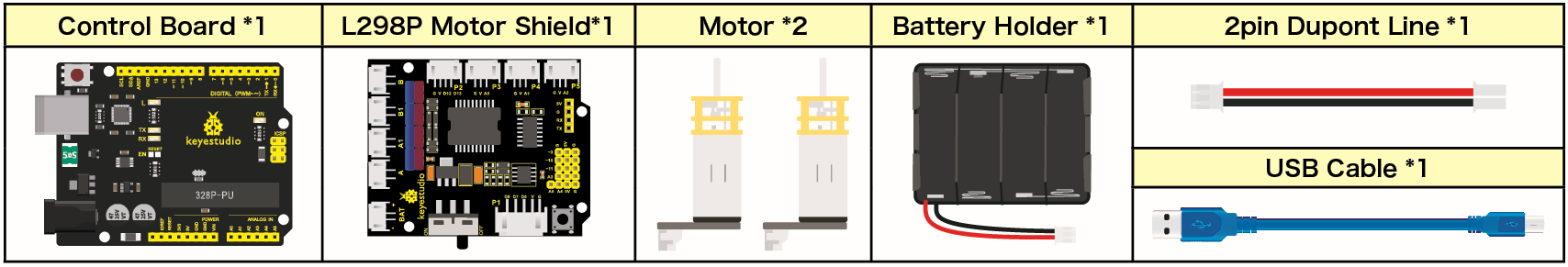
4. Components
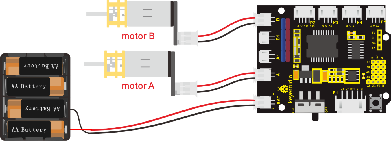
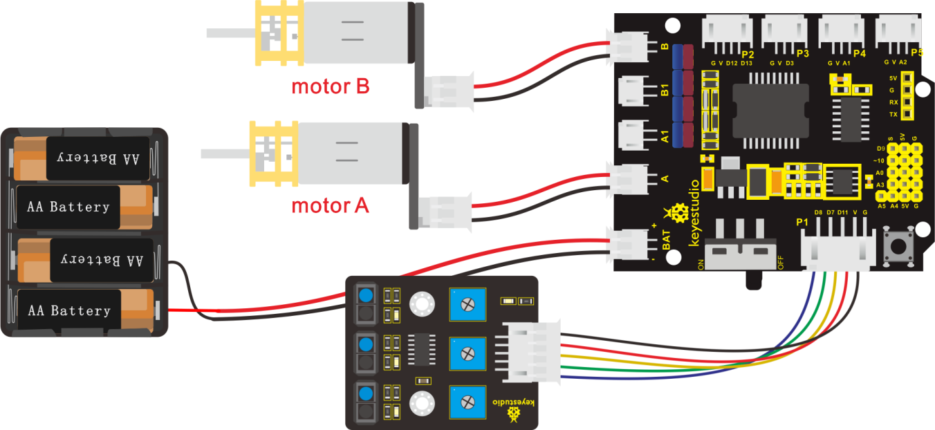
5. Connection Diagram
6. Test Code
The program will be generated if you find the following file and drag it into Mixly software.
File type |
Route |
File Name |
|---|---|---|
MIX File |
../tutorial for Mixly/Mixly Code/lesson_8_Motor Driving and Speed Control |
lesson_8.1_Motor Driving and Speed Control |
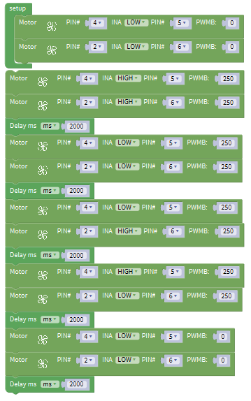
You could edit code step by step as follows:
(1)Click “Control” to get block.
(2) Go to ”Module”→”Drive_Module”→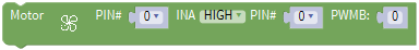 ,
,
(3) Place it into block.
(4) The direction pin and speed control pin of B motor(left) are connected to D4 and D5. So set PIN 4 and PIN 5 as follows:
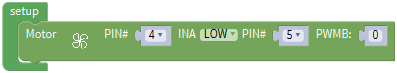
(5) Copy once and place it into block.
(6) The direction pin and speed control pin of A motor (right) are connected to D2 and D9. So set PIN 2 and PIN 9 as follows:
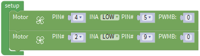
(7) Duplicate code string 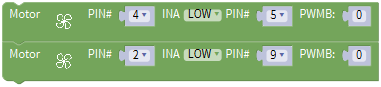 once, set INA to HIGH and PWB to 200:
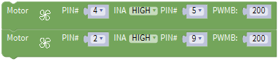
(8) Click “Control” to move out block,delay in 2000ms.
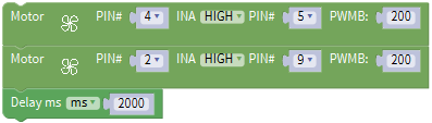
(9) Replicate for four times,then set the code string as follows:
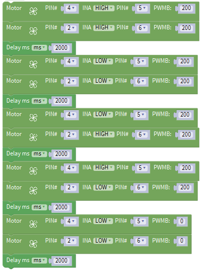
Complete Program:
7. Test Result
Hook up by connection diagram, upload code and power on, smart car goes forward and back for 2s, turns left and right for 2s, stops for 2s and alternately.
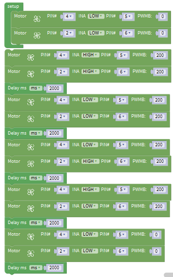
8. Extension Practice
The program will be generated if you find the following file and drag it into Mixly software.
File type |
Route |
|---|---|
MIX File |
../tutorial for Mixly/Mixly Code/ lesson_8_Motor Driving and Speed Control |
File Name |
|
lesson_8.2_Extension Practice |
You could edit code step by step as follows:
Complete Program:
Upload code successfully, the motors rotate slower.
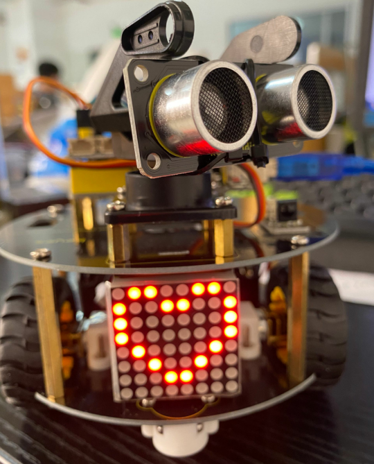
Project 9: 8*8 LED Board

1. Description
A fun way to make a small display is to use an 8x8 matrix or a 4-digit 7-segment display. Matrices like these are ‘multiplexed’ - to control 64 LEDs you need 16 pins. That’s a lot of pins, and there are driver chips like the MAX7219 that can control a matrix for you, but there’s a lot of wiring to set up and they take up a ton of space. After all, wouldn’t it be awesome if you could control a matrix without tons of wiring?
We control and drive 8*8 LED Board by HT16K33 chip, which is convenient for wiring and greatly save the resources of microcontroller.
2. Components
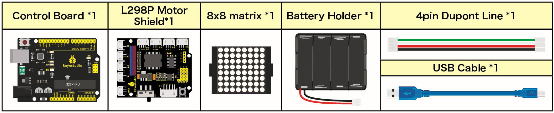
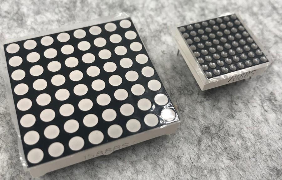 8*8 Dot Matrix
Composed of LED emitting tube diodes, LED dot matrix are applied widely to public information display like advertisement screen and bulletin board, by controlling LED to show words, pictures and videos, etc.
Divided into single-color, double-color, and three-color lights according to emitting color , LED dot matrix could show red, yellow, green and even true color.
There are 4×4, 8×8 and 16×16 different types matrix.
8×8 dot matrix contains 64pcs LEDs.
The inner structure of 8×8 dot matrix is shown below.
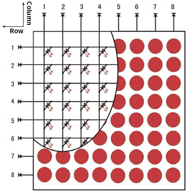
Every LED is installed on the cross point of row line and column line. When the voltage on some line increases, and the voltage on some column line is reduced, the LED on the cross point will light up. 8×8 dot matrix has 16 pins. Put the silk-screened side down and the anticlockwise numbers are 1,8, 9 and 16.
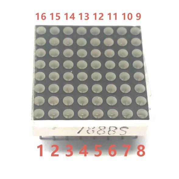
The definition inner pins are shown below:
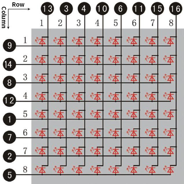
For instance, to light up the LED on row 1 and column 1, increase the voltage of pin 9 and reduce the voltage of pin 13.
3. HT16K33 8X8 Dot Matrix
The HT16K33 is a memory mapping and multi-purpose LED controller driver. The max. Display segment numbers in the device is 128 patterns (16 segments and 8 commons) with a 13*3 (MAX.) matrix key scan circuit. The software configuration features of the HT16K33 makes it suitable for multiple LED applications including LED modules and display subsystems. The HT16K33 is compatible with most microcontrollers and communicates via a two-line bidirectional I2C-bus.
The working schematic of HT16K33 chip
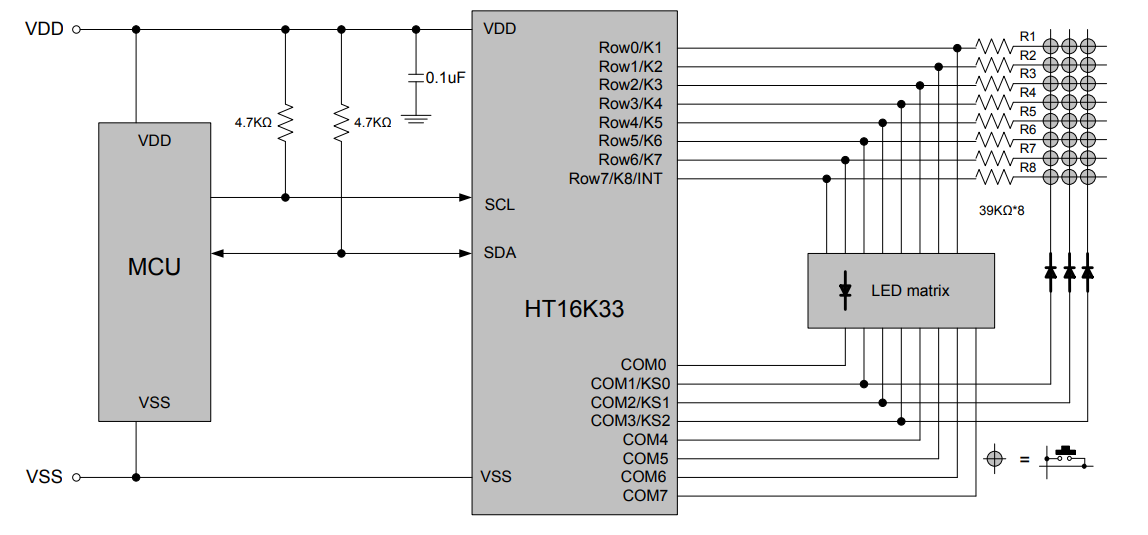
We design the drive module of 8*8 dot matrix based on the above principle. We could control the dot matrix by I2C communication and two pins of micro controller, according to the above diagram.
4. Specification of 8*8 dot matrix
Input voltage: 5V
Rated input frequency: 400KHZ
Input power: 2.5W
Input current: 500mA
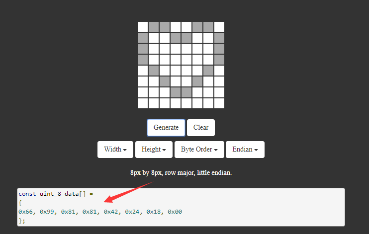
5. Introduction for Modulus Tool
The online version of dot matrix modulus tool:
Open links to enter the following page.
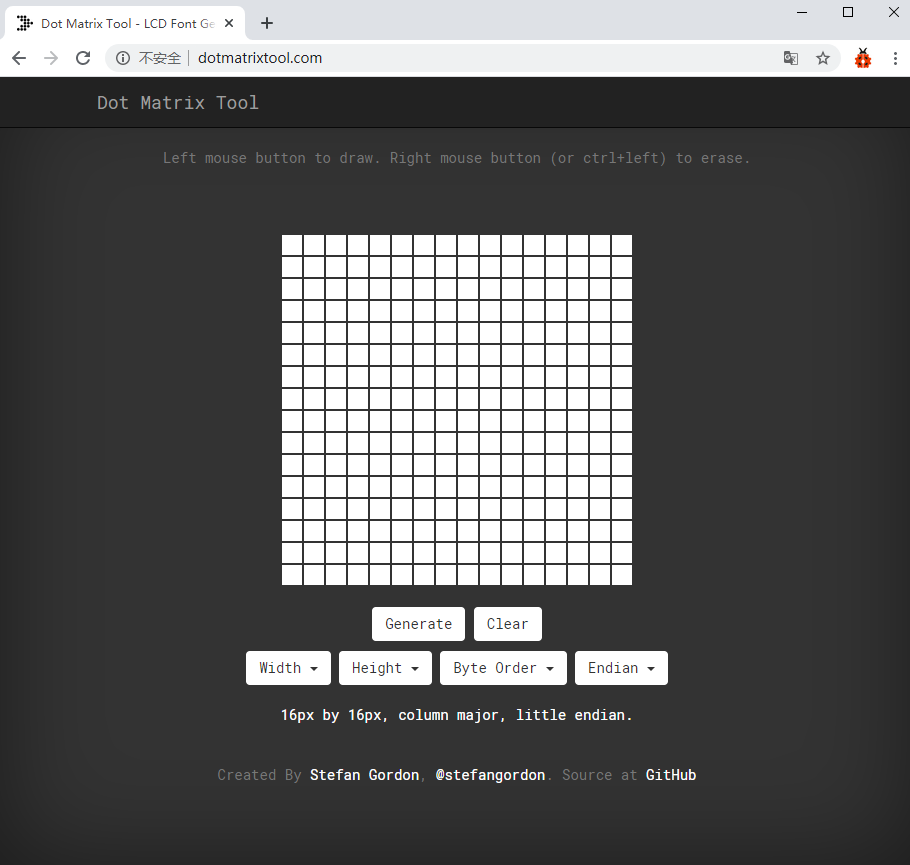
The dot matrix is 8*16 in this project, so set the height to 8, width to 8, as shown below.
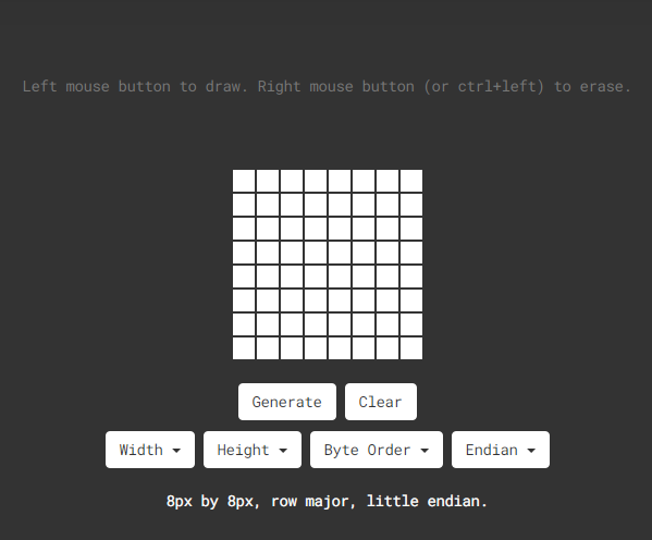
Click Byte order to select “Row major”
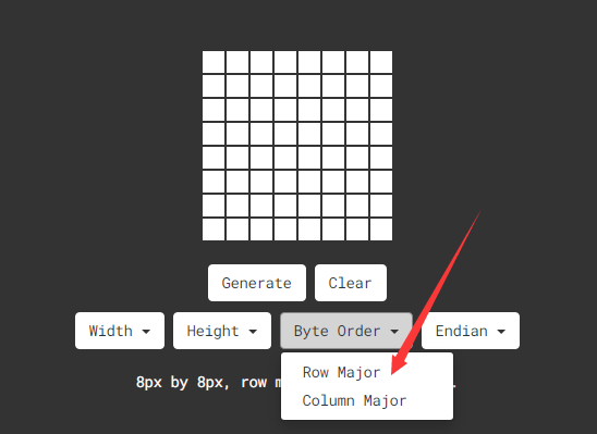
Generate hexadecimal data from the pattern
As shown below, press the left mouse button to select, the right button to cancel, draw the pattern you want, click Generate, and the hexadecimal data we need will be produced.
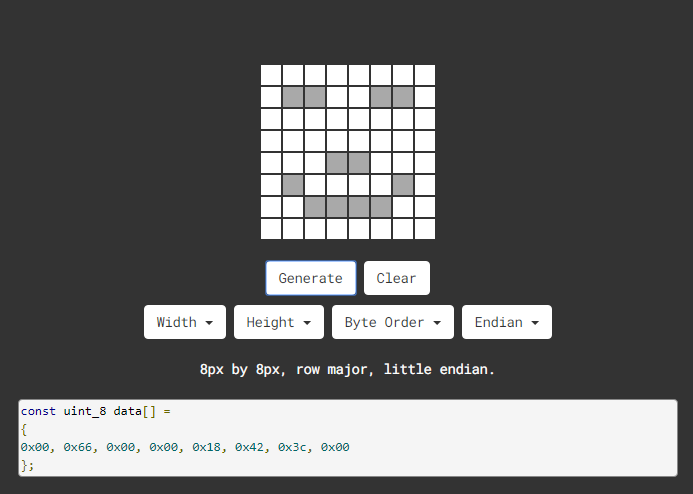
The generated hexadecimal code(0x00, 0x66, 0x00, 0x00, 0x18, 0x42, 0x3c, 0x00) is what we display, and save it.
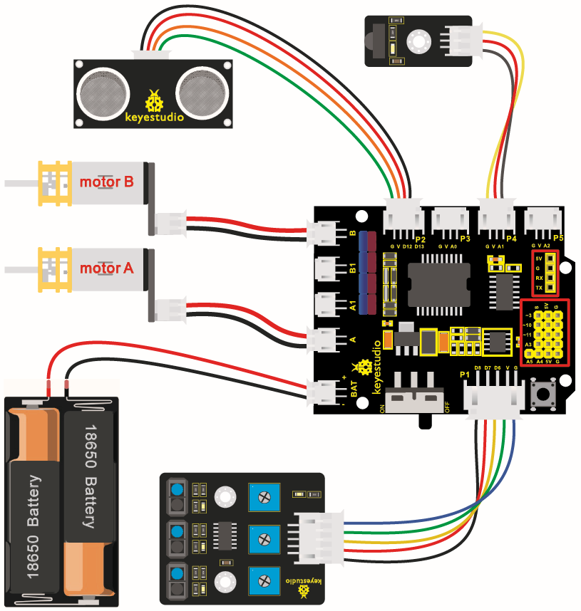
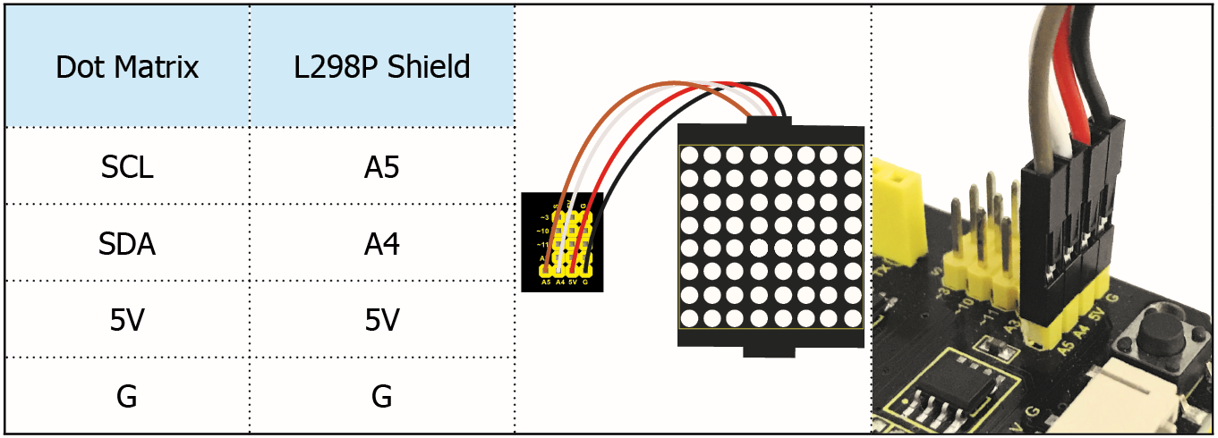
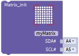
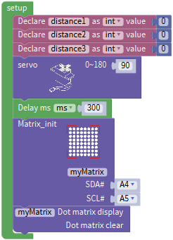
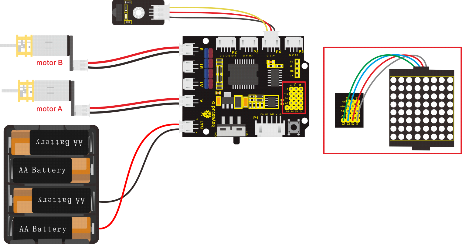
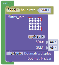
6. Connection Diagram
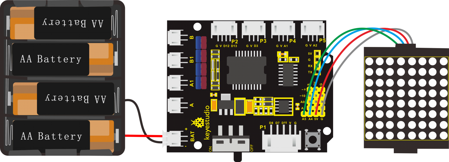
Note: The pin G, V, SDA and SCL of dot matrix module are separately connected to G, 5V, A4 and A5 of motor drive shield. Plug power to BAT interface.
7. Test Code
The program will be generated if you find the following file and drag it into Mixly software.
File type |
Route |
File Name |
|---|---|---|
MIX File |
../tutorial for Mixly/Mixly Code/ lesson_9_8*8 LED Board |
lesson_9.1_8*8 LED Board |
You could edit code step by step as follows:
(1) Click “Control” to get block
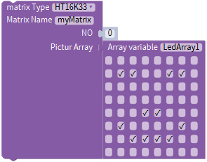
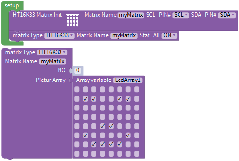
(2) Enter“Module”→”Display_Module”→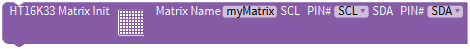
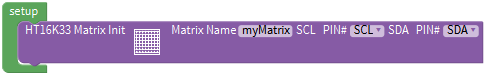
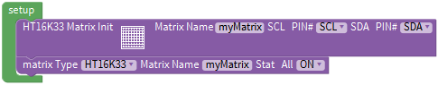
(3) Go to “Display_Module” to get block and leave it into block,and click drop-down triangle button to set“ON”.
(4) Move out block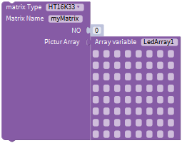 from “Display_Module”,
Tick the white box to light up LED, “√”will appear and generate a smile face pattern. As shown below:
Complete Program:
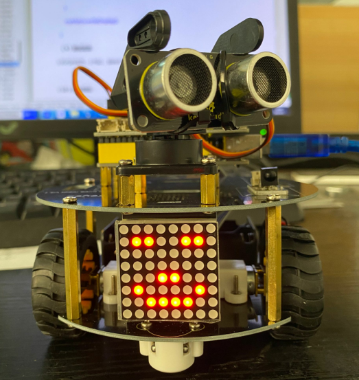
8. Test Result
Upload code, plug in power and turn on switch of smart car, 8*8 dot matrix displays a smile face pattern.
9. Extension Practice
Let’s make dot matrix draw a heart, just enter the website and draw the following pattern.
 ,
,
Then we get the code of heart pattern
Replace the above code of heart pattern, the complete code is shown below:
File type |
Route |
|---|---|
MIX File |
../tutorial for Mixly/Mixly Code/ lesson_9_8*8 LED Board |
File Name |
|
lesson_9.2_Extension Practice |
You could edit code step by step as follows:
Complete Program:

Upload code, plug in power and turn on switch of smart car, 8*8 dot matrix displays a heart pattern.
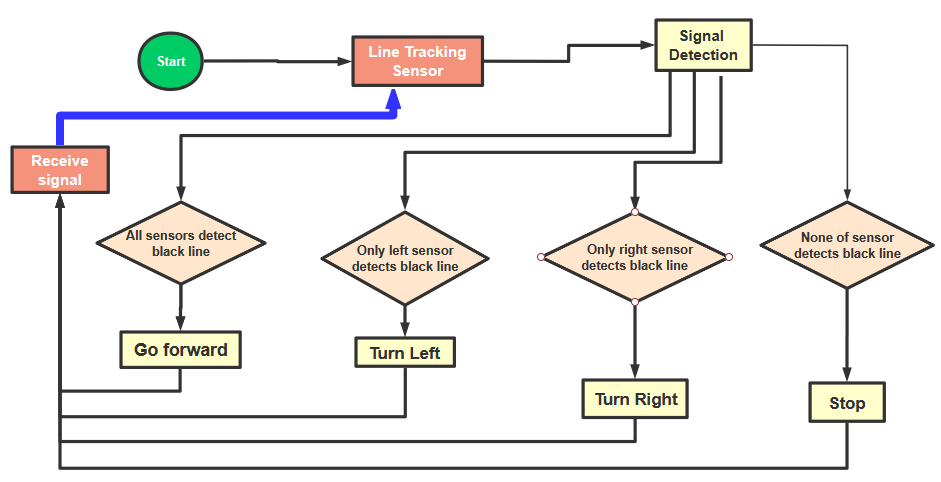
Project 10: Line Tracking Robot
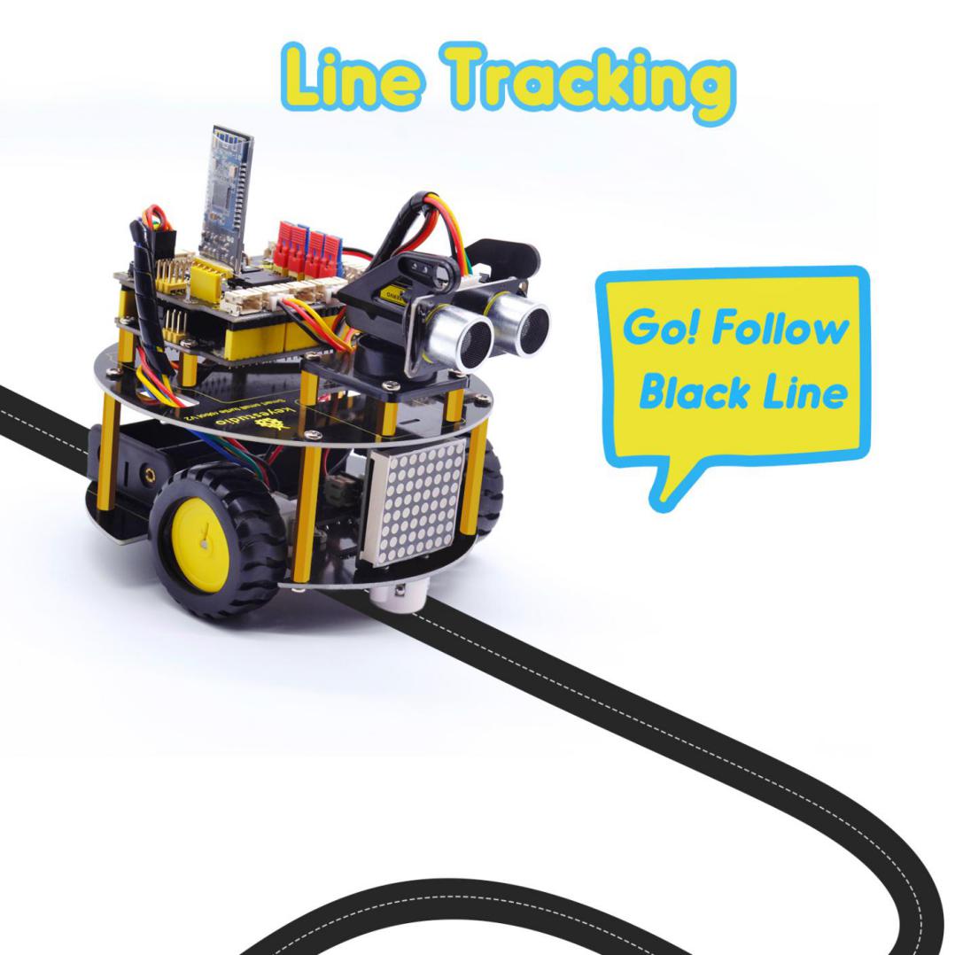
1. Description
The previous projects are inclusive of the knowledge of multiple sensors and modules. Next, we will work on a little challenging task.
We could make a line tracking car on top of the working principle of line tracking sensor.
2. Program Process
Detection |
Middle tracking sensor |
detects black line: HIGH |
|---|---|---|
detects white line: LOW |
||
Left tracking sensor |
detects black line: HIGH |
|
detects white line: LOW |
||
Right tracking sensor |
detects black line: HIGH |
|
detects white line: LOW |
||
Condition 1 |
Status 2 detecting the left and the right tracking sensor |
Status |
Middle tracking sensor detects black line |
left tracking sensor detects black line; right sensor detects white line |
Rotate to left(Set PWM to 200) |
left tracking sensor detects white line; right sensor detects black line |
Rotate to right(Set PWM to 200) |
|
left and right tracking sensor detect black line |
Go front(Set PWM to 200) |
|
left and right tracking sensor detect white line |
Go front(Set PWM to 200) |
|
Middle tracking sensor detects white line |
Only left line tracking sensor detects black line |
Rotate to left(Set PWM to 200) |
Only right line tracking sensor detects black line |
Rotate to right(Set PWM to 200) |
|
Left and right line tracking sensors detect black line |
stop |
|
Left and right line tracking sensors detect white line |
stop |
3. Flow Chart
4. Connection Diagram
5. Test Code
The program will be generated if you find the following file and drag it into Mixly software.
File type |
Route |
File Name |
|---|---|---|
MIX File |
../tutorial for Mixly/Mixly Code/ lesson_10_Line Tracking Robot |
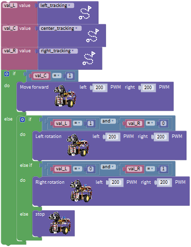
lesson_10_Line Tracking Robot |
You could edit code step by step as follows:
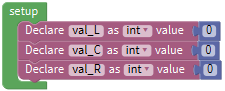
(1) Go to“Control”Module to find out block.
(2) Click“Variables”to move out blockand duplicate it for two times.
(3) Separately change item into val_L, val_C and val_R.
(4) Go to“Math”to move out blockand copy it twice.
(5) Edit the following code string:
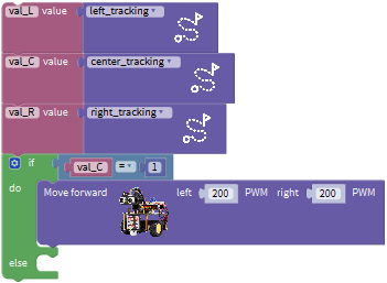
(6) Go to “Variables” to get block.
(7) Tap“robot”→“TurtleCar”to move out block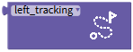
+=
(8) Duplicate blocktwice,then change val_L into val_C and val_R; left_tracking into center_tracking and right_tracking. 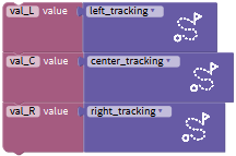
(9) Click“Control”to get block ,click,and moveinto ,thenblock turns intoblock.
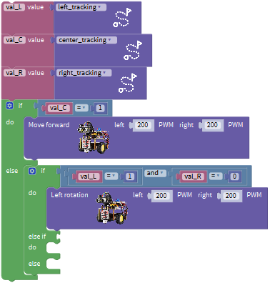
(10) Click“Logic”to move out blockand place it behind if block. Go to“Variables”to drag out block into left box of “=” block,
(11) Copyagain and leave it into right box of“=”b lock,and change 0 into 1.
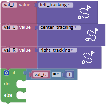
(12) Tap“Robot”→“TurtleCar”→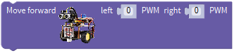
(13) Put it under block val_C=1, and change 0 into 200.
(14) Go to“Control”to move blockinto else block,click,drag block into
into  block and move block
 into block,thenblock turns into block
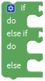 .
.
(15) Click“Logic”to move out block and
(16) Place behind if block, and leavein the left box of “and”block.
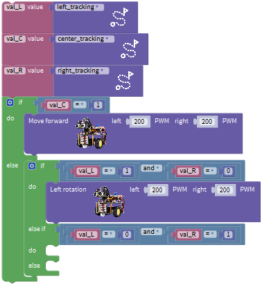
(17) Go to“Variables”to drag out block into left box of“=”block,
(18) Copyagain and leave it into right box of“=”b lock,and change 0 into 1.
(19) Copy block  once and keep it in the right box of “and”block, change val_L into val_R, 1 into 0
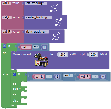
(20) Click “robot” → “TurtleCar” →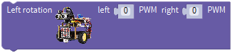
Place it behind the second do block and set to 200 PWM
(21) Replicate block once and leave it behind else if.
(22) Set to“val_L=0 and val_R=0
(23) Click “robot” → “TurtleCar” →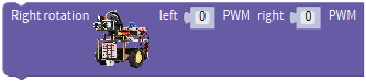 Place it behind the third do block, and set to 200 PWM
(24) Drag out block  and keep it behind the second else block
Complete Program:
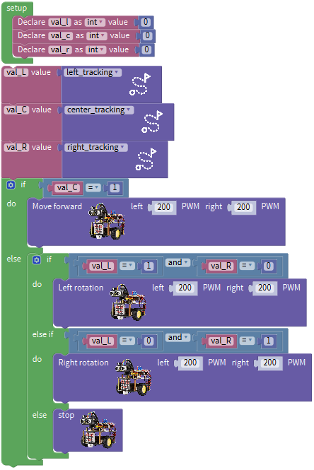
6. Test Result
Upload code on the development board, plug in power and turn on the switch of smart car. The smart turtle car will walk along the black line.
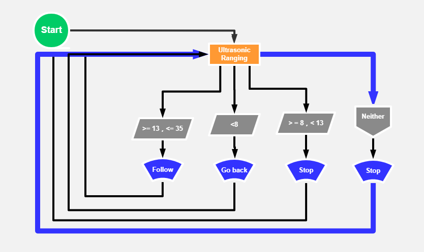
Project 11: Ultrasonic Follow Robot
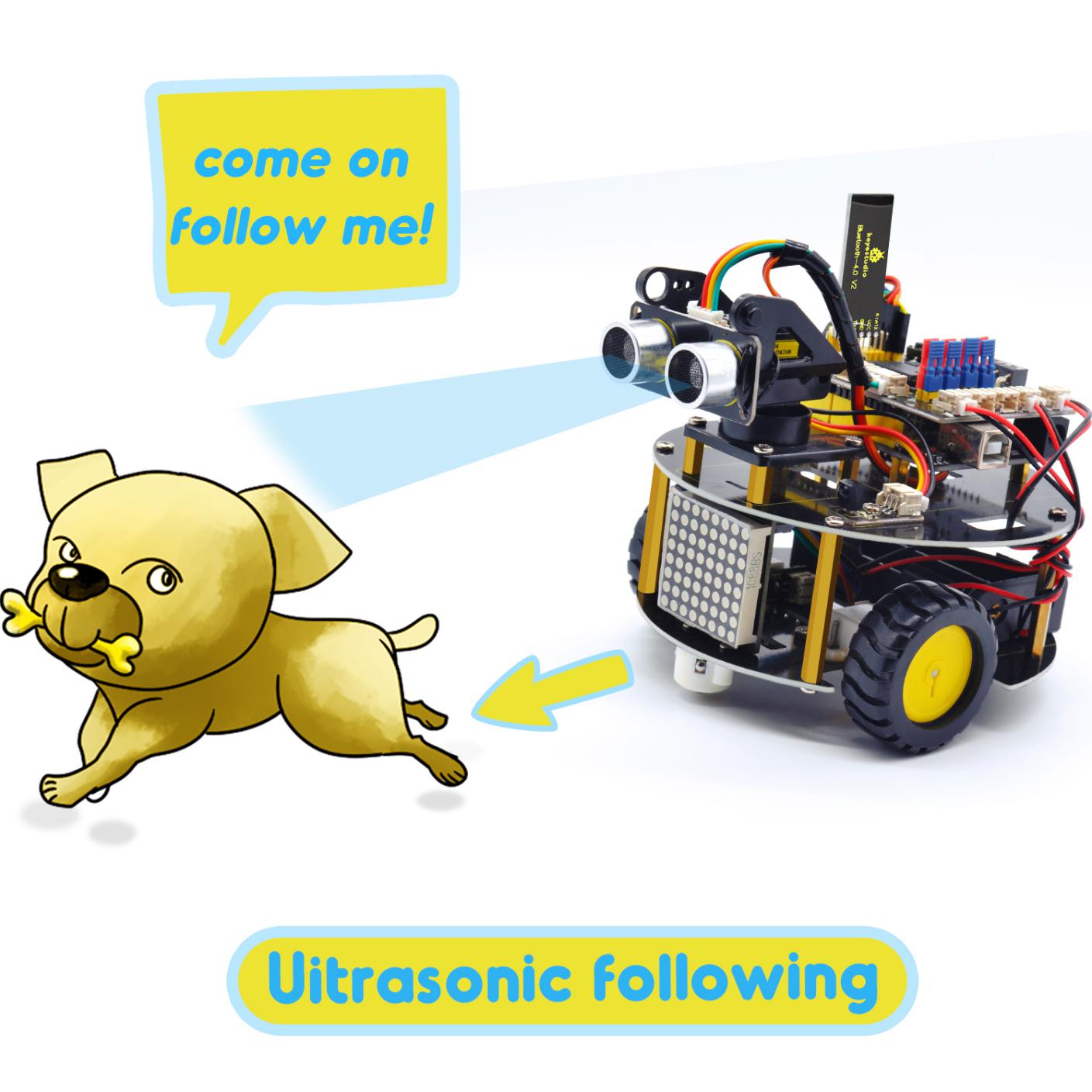
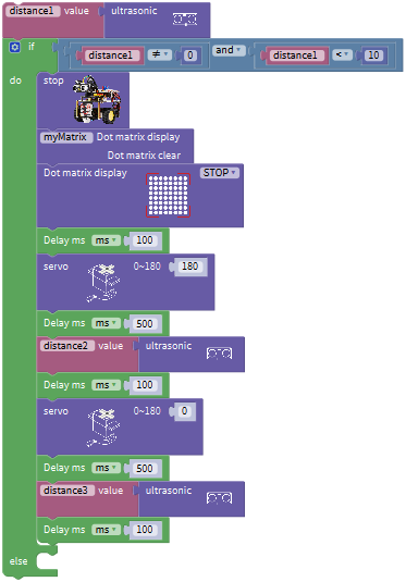
1. Description
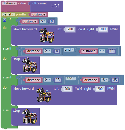
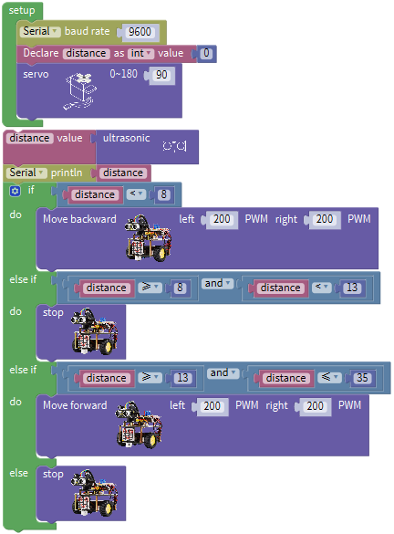
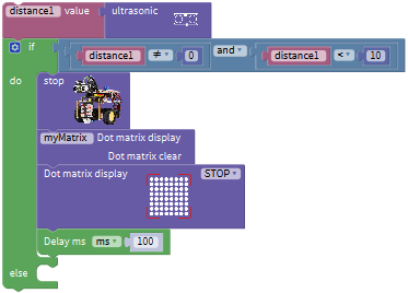
In this project, we detect the distance value of the obstacle to drive two motors so as to make robot car move and 8*8 dot matrix show smile face pattern
Control the motor rotating by measured data, thus control the motion of robot car.
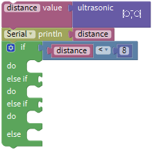
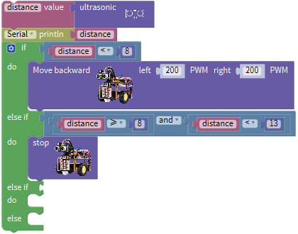
The specific logic of ultrasonic follow robot car is as shown below:
Detection |
Measured distance of front obstacles (distance(unit: cm)) |
|---|---|
Setting |
Set the angle of servo to 90° / Make dot matrix show smile face pattern |
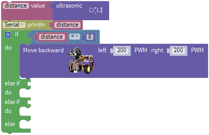
Condition |
Distance<8 |
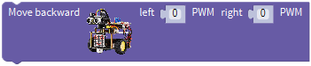
Status |
Go back(set PWM to 200) |
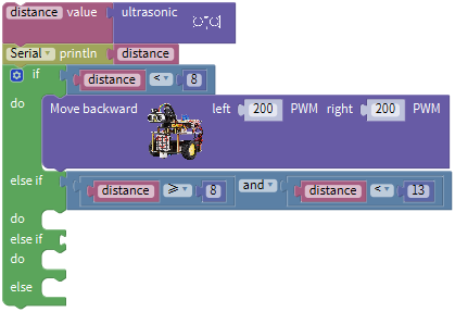
Condition |
distance≥8 and distance<13 |
Status |
Stop |
Condition |
distance≥13 and distance<35 |
Status |
Go front(set PWM to 200) |
Condition |
distance≥35 |
Status |
stop |
2. Flow Chart
3. Program Process
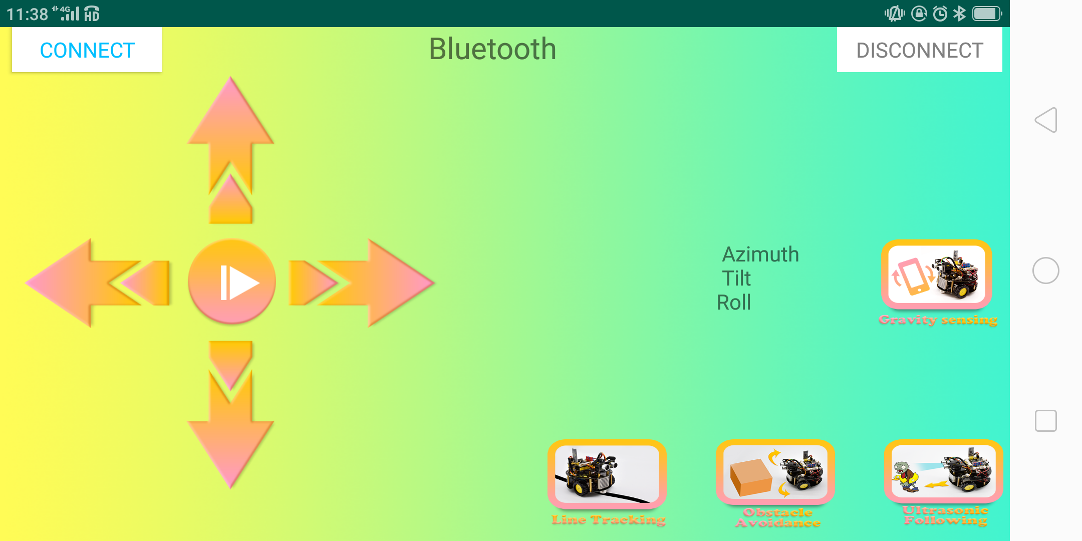
Below is app of turtle robot car interface and we have listed out what function of each key does.
|
Pair Bluetooth module |
|
|---|---|---|
|
Enter control page |
|
|
Disconnect Bluetooth |
|
|
Press: F Release: S |
robot goes front; release to stop |
|
Press: L Release: S |
robot turns left; release to stop |
|
Click to send “S” |
Stop |
|
Press: R Release: S |
robot turns right; release to stop |
|
Press: B Release: S |
robot goes back; release to stop |
|
Click to send “Y” |
Start Ultrasonic follow function |
|
— |
Click to start the mobile gravity sensing; click again to exit |
|
Click to send “U” |
Start ultrasonic avoiding function |
|
Click to send “X” |
Start line tracking function |


4. Flow Chart
5. Connection Diagram

6. Test Code
The program will be generated if you find the following file and drag it into Mixly software.
File type |
Route |
File Name |
|---|---|---|
MIX File |
../tutorial for Mixly/Mixly Code/lesson_11_Ultrasonic Follow Robot |
lesson_11_Ultrasonic Follow Robot |
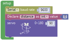
You could edit code step by step as follows:
Enter“Serial Port”to move block
into
+
=
Go to“Variables”to move block
 into block,enter“Math”to drag block
 into block,and change item into distance.
Click“robot”→“TurtleCar”→
Leave it under block “Declare distance as…0”and change 0 into 90
Go to “Variables” to move out block
 . Enter “robot” → “TurtleCar” →
- +=
Go to “serial”to move
 block out, and combine
 with
with
Click “Control” to move out block
,tap ,
, appears, drag into blockfor 2 times and move into if block, then the block
 is produced.
Enter “Logic” to move block
into if blockGo to “Variables” to drag block
into left box of “=”Click “Math” to move out block
into right box of “=”, change 0 into 8, and “=” into “<”.
Click “robot” → “TurtleCar”→
Put it behind “do” block and set to 200 PWM.
Go to“Logic”to move out block
and combine with else if block.Replicate block
 twice and place them at both side of “and” block and edit the code string as follows:
Click “robot” → “TurtleCar” →
Combine it with the second do block.
Copy block once.
once.
Place it behind the second else if block,and edit the code string as below: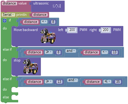
Drag outand 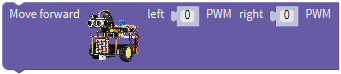 from “TurtleCar”,and finish the code string as follows:
Complete Program:
7. Test Result
Upload the code to the development board, plug in power and turn on the switch of smart car. Adjust the servo on turtle robot car to 90°, robot car will follow the obstacle to move(robot car only moves forward and backward).
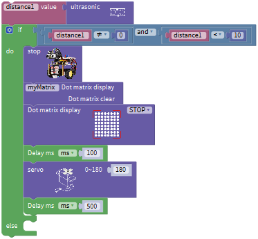
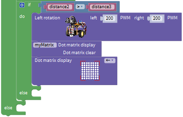
Project 12: Ultrasonic Avoiding Robot
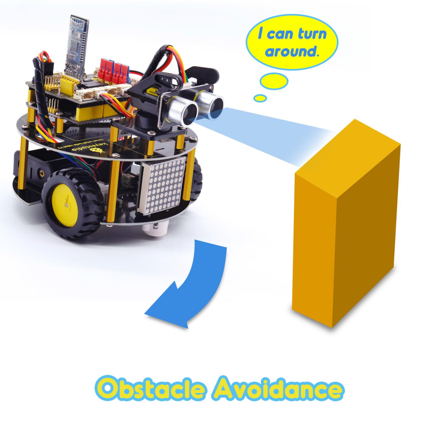
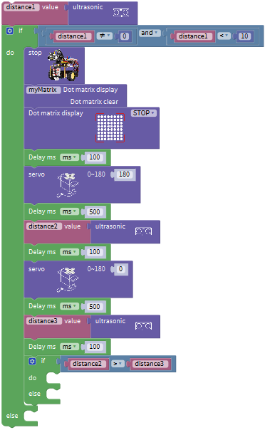
1. Description
We’ve learned LED matrix, motor drive, ultrasonic sensor and servo in previous lessons. Next, we could make an ultrasonic avoiding robot!
The measured distance between ultrasonic sensor and obstacle can be used to control servo to rotate so as to make robot car move.
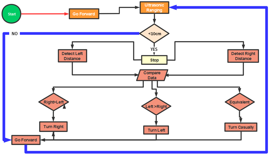
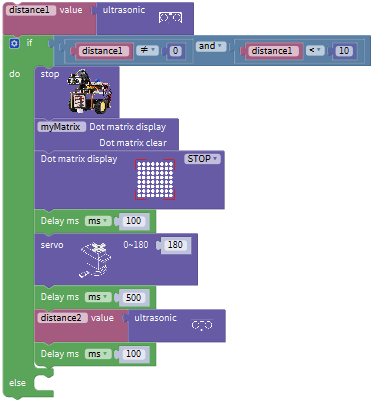
The specific logic of ultrasonic avoiding smart car is as shown below:
Detection |
a(unit: cm) |
measured distance of front obstacle set servo to90° |
|---|---|---|
a1(unit: cm) |
measured distance of left obstacle(set servo to 180°) |
|
a2(unit: cm) |
measured distance of right obstacle(set servo to 0°) |
|
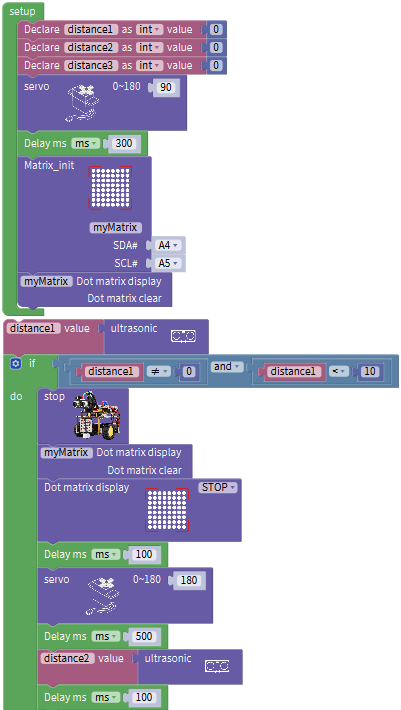
Setting |
set the initial angle of servo to 90° |
|
Dot matrix shows smile face pattern |
||
Condition 1 |
Status |
|
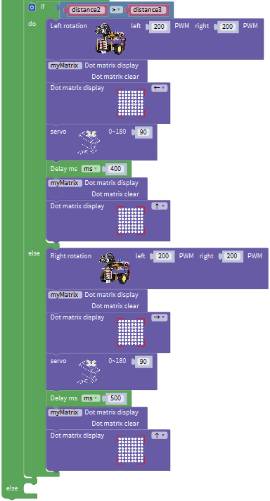
a<10 |
Stop for 1000ms; |
set the angle of servo to 180°,read a1,delay in 500ms;set the angle of servo to 0°,read a2,delay in 500ms |
Condition 2 |
Status |
|
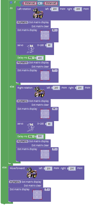
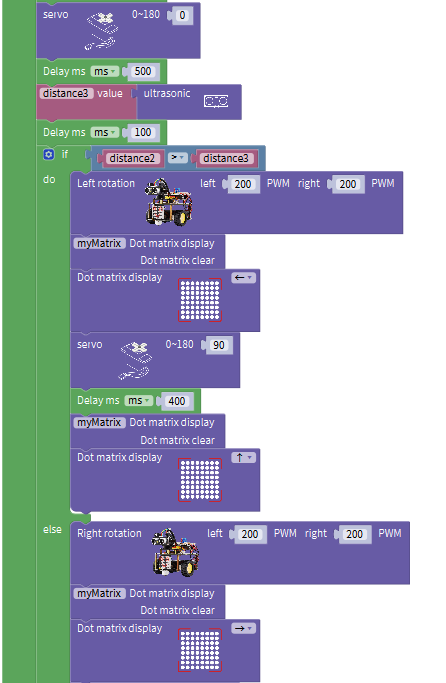
a1>a2 |
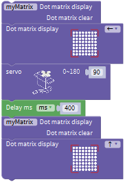
Set the angle of servo to 90°,rotate to left for 400ms (set PWM to 200),and go font(set PWM to 200) |
|
a1≤a2 |
Set the angle of servo to 90°,rotate to right for 400ms,(set PWM to 200,and go front(set PWM to 200) |
|
Condition 1 |
Status |
|
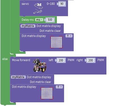
a≥10 |
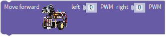
Go front(set PWM to 200) |
2. Flow Chart
3. Connection Diagram
4. Test Code
The program will be generated if you find the following file and drag it into Mixly software.
File type |
Route |
File Name |
|---|---|---|
MIX File |
../tutorial for Mixly/Mixly Code/lesson_12_Ultrasonic Avoiding Robot |
lesson_12_Ultrasonic Avoiding Robot |
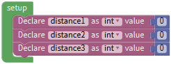
You could edit code step by step as follows:
Go to “Control” to find out block
.Separately change item into distance1, distance2 and distance3.
Go to “Math” to move out block
and copy it for three timesEdit the following code string:
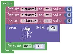
Enter “robot” → “TurtleCar” →
, change 0 into 90 .Drag out
from“Control”and delay in 300ms.Edit the code string as follows:
Then move out block
 and
and and place them into block.
Go to “Variables” to drag out block
 ,and move out
  from “TurtleCar”.
+=
Click “Control” and drag it into block
,click and moveinto then we get block.Go to “Logic” to get
and .Place
into if block,and leave in the left box of block.Enter “Variables” to get block
and keep it at left box of block “=”.Go to “Math” to move out
into right box of block “=”, change “=” into“≠”. Replicate block once and set code string as follows:
Go to “robot” → “TurtleCar”→
 , and
, and
Place them behind the block
 ,
,Click
 to select“STOP”,and move out and set to 100ms. As shown below:
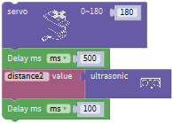
Click “robot” → “TurtleCar” →
, change 0 into 180.Copy
once and set to 500ms.Edit the code string as follows:
Duplicate block
andChange distance1 into distance2, and 1000 into 100.
Finish the following code string as follows:
Duplicate code string
 once and change 180 into 0, distance2 into adistance3.
Place it under block “Delay ms 100”
Click “Control” and drag it into block
,click and move into then we get block.Go to “Logic” to move out block
 into if block,then click“Variables”to drag block
 into left box of“=”block,and move block
 into right box of“=”,and change“=”into“>”.
Find out block
 , and from”TurtleCar”
Place them behind do block of code string
 .
.Set to 200 PWM and click
to select“←”
Move out block
and leave it under block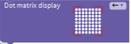 and change 0 into 90.
Copy block
and set to 400ms, as shown below:
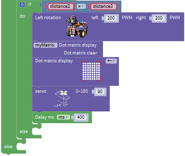
Then drag out block
and Place them below block “delay ms 400” and tap
to choose“↑”.
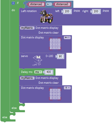
Go to “TurtleCar” to move block
 behind else block,
Copy code string
 once and place it into else block.
Set to 200 PWM and delay in 500ms. Click“←”to choose“→”.
Move out block
 , and
, andChange 0 into 200, click
to select“↑”.Leave the above blocks into else block, as shown below:
2. Complete Program:
5. Test Result
After uploading the code on the keyestudio V4.0 board, wire according to connection diagram. Turn on the switch of robot car, the smart car can automatically avoid obstacles.
Project 13: IR Remote Control Robot
1. Description
In this project, we will make IR remote control robot car!
Press the button on IR remote control to drive robot car to move, and the corresponding state pattern is displayed on the 8*16 LED matrix.
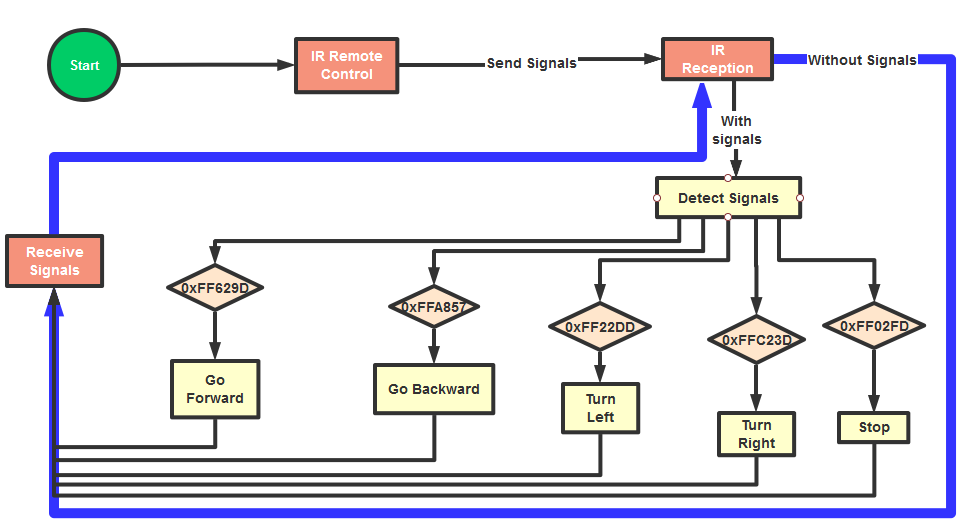
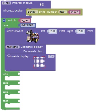
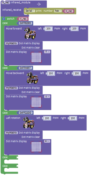
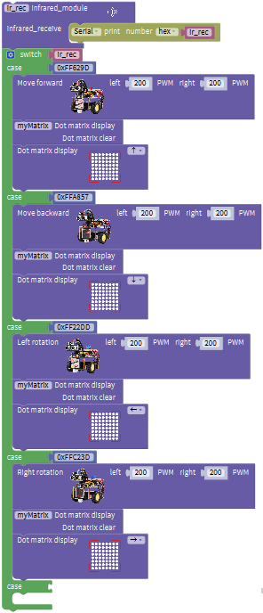
The specific logic of IR remote control robot car is shown below:
Initial setup |
8X16 LED matrix Clear |
|
|---|---|---|
Remote control |
Key Value |
Key state |
|
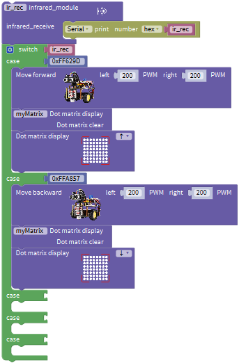
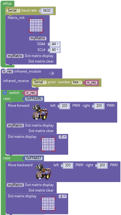
FF629D |
Go front(PWM set to 100) |
8*8 LED matrix shows front icon |
||
|
FFA857 |
Back(PWM set to 100) |
8*8 LED matrix shows back icon |
||
|
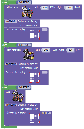
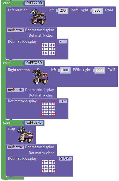
FF22DD |
Rotate to left(PWM set to 200) |
8X16 LED matrix shows leftward icon |
||
|
FFC23D |
Rotate to right(PWM set to 200) |
8X16 LED matrix shows rightward icon |
||
|
FF02FD |
Stop |
8X16 LED matrix shows“STOP” |


2. Flow Chart
3. Connection Diagram
Note: IR receiver is connected to P4 interface.
4. Test Code
The program will be generated if you find the following file and drag it into Mixly software.
File type |
Route |
File Name |
|---|---|---|
MIX File |
../tutorial for Mixly/Mixly Code/ lesson_13_IR Remote Control Robot |
lesson_13_IR Remote Control Robot |
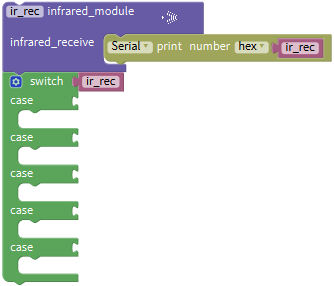
You could edit code step by step as follows:
(1) Click“Control” to get block
(2) Enter“Serial Port”to move blockinto
+=
(3) Go to “robot” →”TurtleCar”→block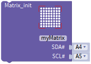 and
and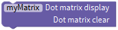 , combine them with block
(4) Enter “robot” → “TurtleCar”→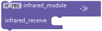 ,then click “SerialPort” to drag block
 into block,
(5) Tap “Variables” to move block into blank box of block
(6) Click“Control”to move out block ,click,tap,
 appears, drag
  into block
 for 5 times,the block
 is produced.
(7) Click “Variables” to move blockbehind block“switch”.
(8) Go to“Math”to get block and put it behind the first block case,change a into 0xFF629D;
(9) Enter “robot” → “TurtleCar”→ , and
, and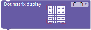
(10) Place the above blocks under the first block case, change 0 into 200,and click to select“↑”
(11) Go to“Math”to get blockand put it behind the second block case,change a into 0xFFA857;
(12) Enter “robot” → “TurtleCar”→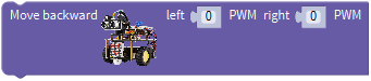 , and
, and
(13) Place the above blocks under the second block case, change 0 into 200,and click to select“↓”.
 (14) Go to“Math”to get blockand put it behind the third block case,change a into 0xFF22DD;
(15) Enter “robot” → “TurtleCar”→ , and
, and
(16) Place the above blocks under the third block case, change 0 into 200,and click to select“←”.
(17) Go to“Math”to get blockand put it behind the fourth block case,change a into 0xFFC23D;
(18) Enter “robot” → “TurtleCar”→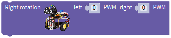 , and
, and
(19) Place the above blocks under the fourth block case, change 0 into 200,and click to select“→”.
(20) Go to“Math”to get blockand put it behind the fifth block case,change a into0xFF02FD;
(21) Enter “robot” → “TurtleCar”→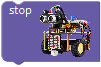 , and.
(22) Place the above blocks under the fourth block case, change 0 into 200,and click to select“STOP”.
Complete Program:
5. Test Result
Upload the code and press the buttons on IR remote control to make turtle car show different motion.
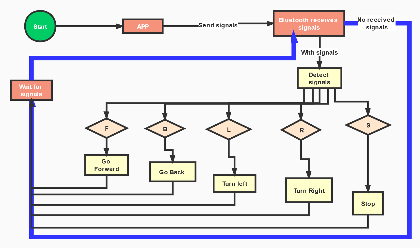
Project 14: Bluetooth Control Robot
1. Description
We’ve learned the basic knowledge of Bluetooth, in this lesson, we will make a Bluetooth remote smart car. In the experiment, we default the HM-10 Bluetooth module as a Slave and the cellphone as a Host.
keyes BT car is an APP rolled out by keyestudio team. You could control the robot car by it readily.
Special Note: you need to remove the Bluetooth module before uploading the test code, otherwise the test code will fail to upload.
Reconnect the Bluetooth module, after uploading code successful.
The program will be generated if you find the following file and drag it into Mixly software.
2. Test the key value of app
Special Note: Before uploading the test code, you need to remove the Bluetooth module, otherwise the test code will fail to upload. After the code is uploaded successful, then reconnect the Bluetooth module.
The program will be generated if you find the following file and drag it into Mixly software.
File type |
Route |
File Name |
|---|---|---|
MIX file |
../tutorialforMixly/MixlyCode/ lesson_14_Bluetooth Remote Control |
lesson_14.1_Bluetooth Reads Data |
You could edit code step by step as follows:
(1) Go to“Control”Module to find out block.
(2) Enter“Serial Port”to move blockinto
+=
(3) Go to “robot” → “TurtleCar”→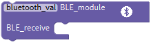 .
.
(4) Click “SerialPort” to move block  into ;enter “Variables” to drag block
 into
into
Complete Program:
Upload code to keyestudio V4.0 development board and connect Bluetooth module, as shown below:
After inserting a Bluetooth module, LED on Bluetooth module will flash. Next to download the App.
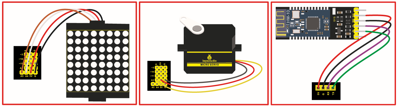
The pin RXD, TXD, GND and VCC of Bluetooth module are connected to TX, RX, -(GND)and +(VCC)on motor drive board. The pin STATE and BRK don’t need to be linked.
The pin G, V, SDA and SCL of dot matrix are linked with pin G, 5V, A4 and A5 of motor drive board. The power is plugged in BAT interface.
3. iOS system
Search keyes BT car in App store
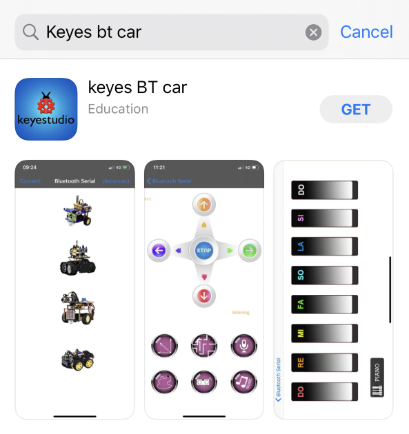
After installation, enter its interface.
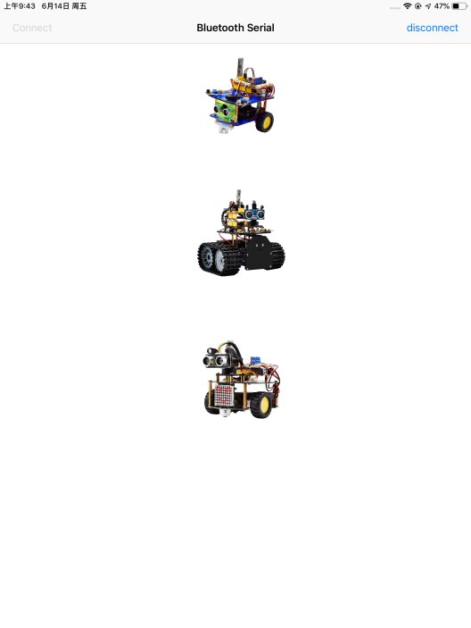
Click“Connect”to search and pair Bluetooth.
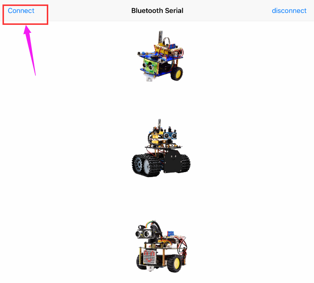
Clickto enter the main page of
turtle smart car.
4. Android System
Enter Google play store to search Turtle Car(allow APP to access“location”, you could enable “location”in settings of your cellphone.
The app icon is shown below after installation.
Click app to enter the following page.
After connecting Bluetooth, plug in power and LED indicator of Bluetooth module will flash. Tap to search Bluetooth.
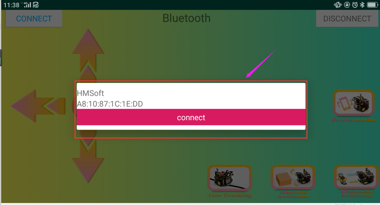
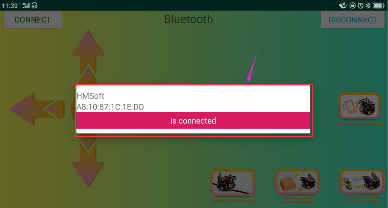
Click“connect”below HMSoft, then the Bluetooth will be connected and its LED indicator will stay on.
After connecting Bluetooth module and open serial monitor to set baud rate to 9600. Press icon on APP, and the corresponding characters are displayed as shown below:
5. Hook-up Diagram
6. Test Code
The program will be generated if you find the following file and drag it into Mixly software.
File type |
Route |
File Name |
|---|---|---|
MIX File |
../tutorial for Mixly/Mixly Code/lesson_14_Bluetooth Remote Control |
lesson_14.1_Bluetooth Control Smart Car |
You could edit code step by step as follows:
(1) Click “Control” to find out block.
(2) Enter “Serial Port” to move blockinto
+=
(3) Enter “robot” →”TurtleCar”→and ;
(4) Place them into block.
(5) Enter “robot” → “TurtleCar”→ ,go to “SerialPort” to move block
 into block; and click “Variables” to drag block
 behind block.
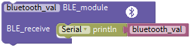
(6) Click“Control”to drag out block,clickand appear box,drag blockfor five times and place them into block,then we get block;
(7) Click “Variables” to place blockbehind the block“switch”
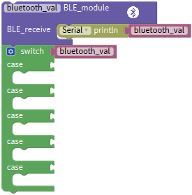
(8) Click “Text” to move block out and keep it behind the first case block,change a into F;
(9) Click “robot” → “TurtleCar”→, and
(10) Place them under case block, change 0 into 200 and tapto select“↑”.
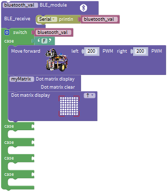
(11) Copy blockand place it behind the second case,alter a into B;Go to “robot” → “TurtleCar”→,and
(12) Put the above blocks under the second case block, change 0 into 200 and click to select“↓”.
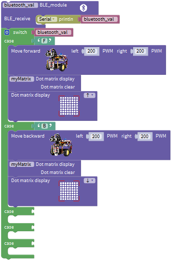
(13) Replicate blockonce and leave it behind the third case block,modify a into L;
(14) Click “robot” → “TurtleCar”→,
and
(15) Put the above blocks under the third case block, change 0 into 200 and tap to choose“←”.
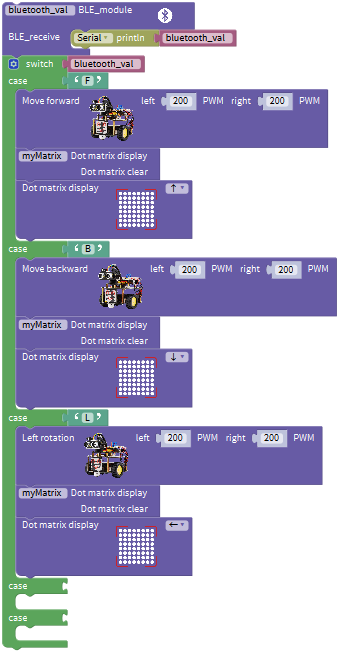
(16) Replicate twice and place them behind the fourth and fifth case blocks respectively.
(17) Go to “robot” → “TurtleCar”→,
,
,
,
and
.
(18) Change 0 into 200, click to select“→”and“STOP”, a into R and S.
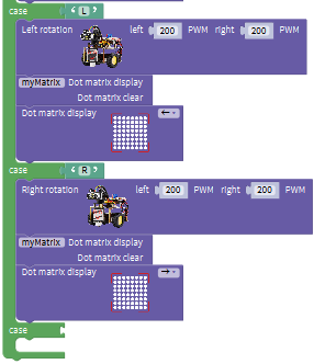
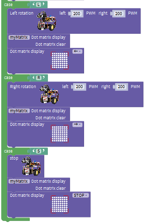
Complete Program:
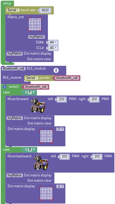
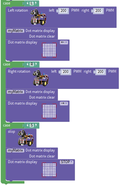
7. Test Result
Upload program to development board, insert Bluetooth module, open App to connect Bluetooth. Next, press icons on App to control turtle robot car to move.
Special Note: you need to remove the Bluetooth module before uploading the test code, otherwise the test code will fail to upload. Reconnect the Bluetooth module, after uploading code successful.
Project 15: Multi-purpose Bluetooth Robot
1. Description
In previous projects, the robot car only performs single function, however, in this lesson, we integrate all of function to control smart car via Bluetooth
Here is a simple flow chart of multi-purpose robot car as for your reference.
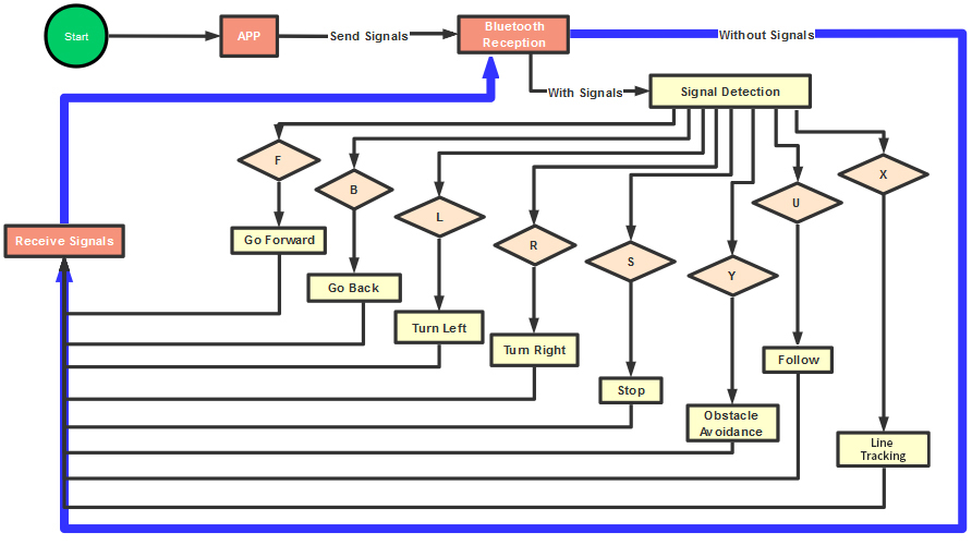
2. Connection Diagram
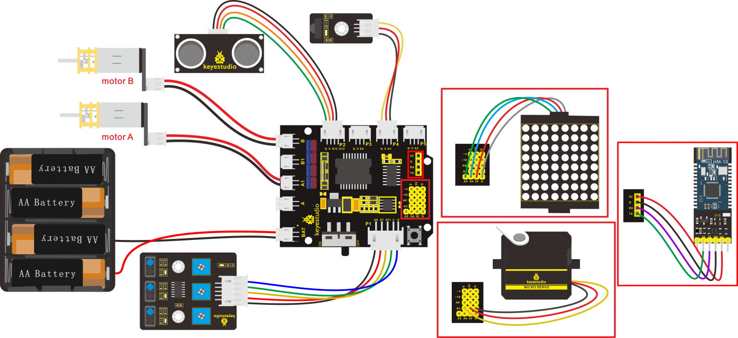
3. Test Code
The program will be generated if you find the following file and drag it into Mixly software.
File type |
Route |
File Name |
|---|---|---|
MIX File |
../tutorial for Mixly/Mixly Code/lesson_15_Multi-purpose Bluetooth Robot |
lesson_15_Multi-purpose Bluetooth Robot |
Complete Program:
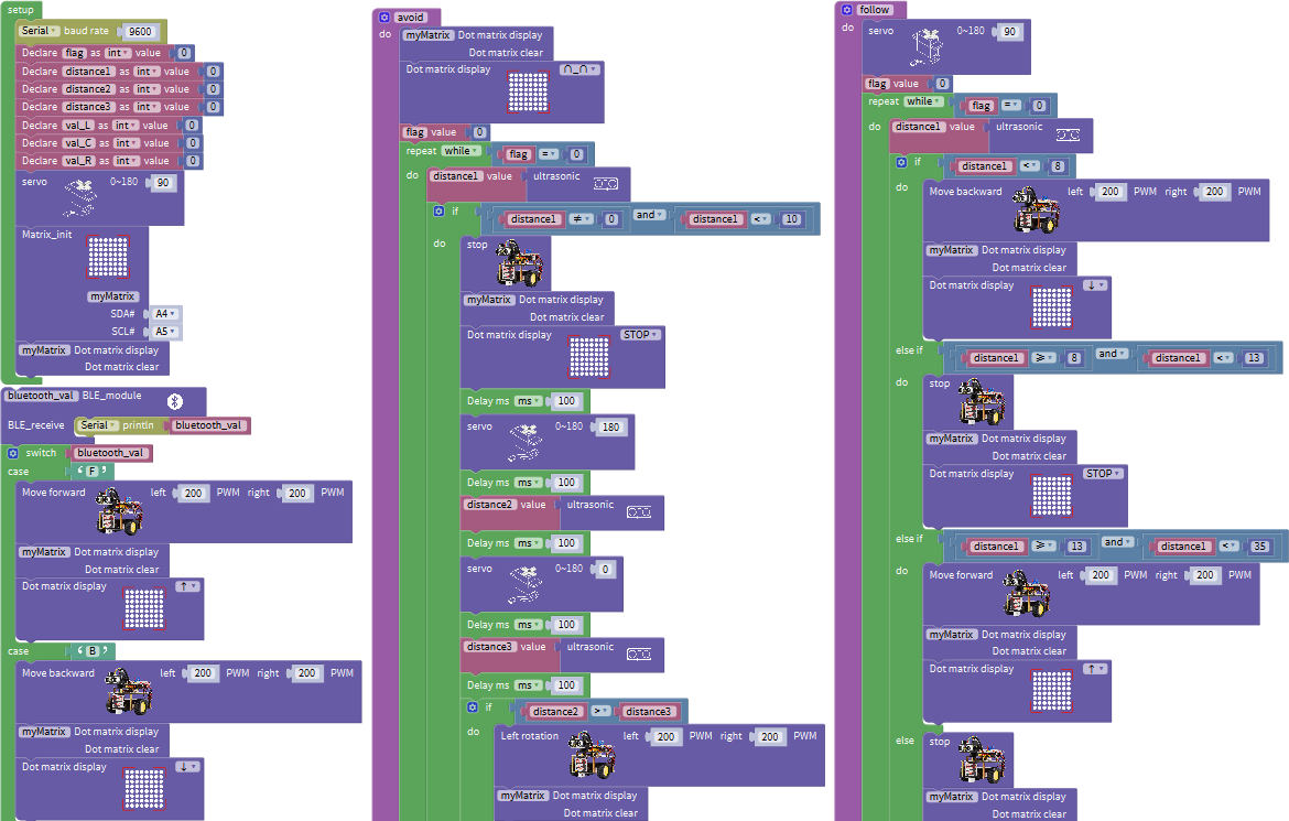
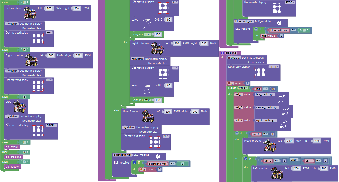
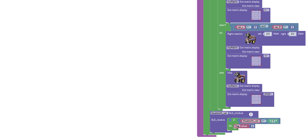
4. Test Result
Upload the code on the keyestudio V4.0 board. Turn on the switch on robot car. After connecting to Bluetooth, we could control turtle robot car via App.
8. Resources
Wiki page: https://wiki.keyestudio.com/Main_Page
Official website: https://keyestudio.com/